


Hit your browser "Refresh" if the page looks untidy.
You need to fast scroll, such as with a mouse.
( research on next year's boats.
e.g. the
MicroMite
,
Drones
,
Sailing Saucers
, and
Windmill Boat
:-)
Earlier experimental work from 2008 to 2015 is now in
BlogX1.
You probably reached this "BlogX" page from that called
Snoopy,
BlogX1,
or the
Design page
.
Click on a link to know more.
Each "blog" page describes detailed work preparing for the next Atlantic Attempt.
i.e. covering a period in the region of a year: less if more than one attempt is made.
The Blog pages were started after the first 2012 Attempt, where Snoopy's boat was lost. All later attempts were
with the same boat, sometimes after major repairs. The blogs provide online "Engineering Notebooks",
providing a day-by-day account of repairs, changes, and testing: mostly testing.
 These blog pages are mostly about numerous repairs to the boat, results from "BRAY LAKE TEsts", or 24/7 reliability testing on Bray Lake.
i.s. Snoopy sailing back and forth over a 24/7 waypoint in "Snoopy Corner". This is typically for several weeks,
in all weather, including gale force winds.
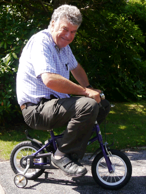
Sometimes, a few things happened which resulted in amusing pictures or stories,
such as countering human-intervention, or testing the wheels for Snoopy's trolly.
Click on the pictures either side for larger versions, or visit earlier blogs above.
This "BlogX" and
BlogX1, the "blog of experiments", show ideas and products for
future boats.
Snoopy's robot boat experiments started in 2008, but it was not until 2012 that we had a boat suitable to make an attempt on the Atlantic. The Design Page was created in late 2012, to document our design, to support building of the next boat. This page soon became a "blog", recording the stages of construction and test. These soon became so big, that they had to be split into different blog pages, each describing the construction, test and repairs, of the next boat to be "thrown into the Atlantic". The latest blog is in the current Blog Page.
We never did have a blog of our experiments, probably because we made so many mistakes, and changed things, much faster than we could document them ! :-) However, my friends and "Team Members" suggested such an "experimental blog" might be of use, so here it is, and we put "experimental stuff" here, rather than in the blogs dedicated to the actual boats being prepared for Atlantic Attempts.
The "Bray Lake Test" has been the same "first challenge", since we started our first experiments in 2008. It took years to achieve success !


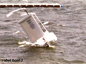
 We started with small boats, with the autopilot based on a Pocket PC, controlling a wind vane, which controlled the rudder.
We always knew that electrical power for electronics was a key issue, probably having to be provided by solar panels,
and vane-rudder steering seemed the obvious solution, since the GPS and other electronics, might be switched off for long
periods.
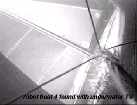
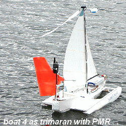
During these early years, we also experimented with different types of boat, starting with small monohulls, such as Boats 1 and 2, then trying others, such as a "sawn off surfboard" (Boat 3) and trimarans - Boat 4, which started as a standard International One Metre (IOM) hull, but was later modified to a trimaran.
In late 2009, we had an interesting diversion, searching for boat 4 with an underwater TV camera ! Video of this, and lots more, is on the 2008 to 2010 Page.
 Boat 5 was larger - about 1.2m / 4 feet long, was also changed into a trimaran, and was the first to pass "The Bray Lake Test".
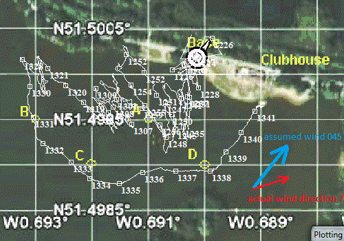 On the right is the GPS Plot of this first Bray Lake Test success, on Friday 13th May 2011 - not so unlucky after all ! :-)
The GPS Plot was recorded by the same GPSSppc for Pocket PC program, used to provide the autopilot, by turning the wind vane, which then steered the boat.
Work then started on trying to make a boat that might be suitable to cross the Atlantic. We soon found that it was difficult to design and make a wind vane based system, that would work in a wide range of wind speeds. e.g. from 5mph to 25mph and more. If the vane were big enough to work in a light wind, our wind vane servo struggled to turn it in a strong wind. Even if that problem were solved, it would be difficult to make the system robust enough, to survive months of continuous use.
We thought of a "wind vane clutch", but did not pursue it, because we were soon having success with the experimental "GPS-only autopilot". This had been suggested by John years earlier: simply using the GPS based direction of movement as an indication of the direction the boat was heading, and for the autopilot to steer the boat in the correct direction, with a rudder servo.
 By then we had plenty of GPS plots, and Bray Lake Tests, where we had heard
the autopilot speaking information such as the GPS-based direction to steer
- even though the steering was done using the vane rudder.
e.g. "steer right 15 degrees".
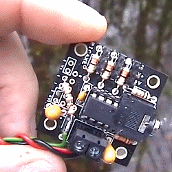
This was also when we decided to try and squeeze the autopilot software into a Picaxe 08M2 computer (on left), and Boat6 was built as the testbed. That's boat 6 having it's first taste of salt water below. The new Picaxe based, GPS-Only autopilot worked well, and we were soon working on Boat 7, then Boat 8, with solar panels, towards a sea-worthy boat, and our first attempt on the Atlantic in late 2012.
More detail of these years is on the 2011 to 2012 Page. It was not until late 2012 that we set up the Design Page and 2013, before we started what are now the Blog1, Blog2, and (current) Blog pages. Practically all the "experimental" work described on these "blog" pages relates to finding and fixing problems with boats preparing to make an Atlantic attempt. This is the new "BlogX" page, started in late 2014, for experimental work.

All our boats, used for 2012, 2013, and 2014 Atlantic Attempts, had the same design: the following section is near the start of our Design Page....
Experimental prototypes first sailed, on Bray Lake, in 2008, but it was not until 2012, that we had settled on the current design, used in all our Atlantic attempts so far:
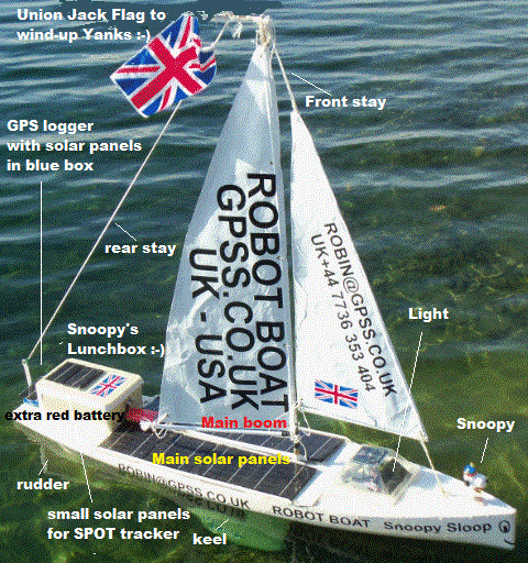
All products used within a boat will have undergone months, sometimes years, of experimental test, before weeks or months of 24/7 test, before an Atlantic attempt. Please do not confuse what we are doing experimentally, for possible use in future boats, with our "current design" above. e.g. experiments with boat 6 to test things like compass-based steering, use of wind direction sensors, etc.
Remember that the biggest challenge to a robot boat crossing the Atlantic is reliability: maybe the most useful thing to remember is "KISS" - Keep it Simple, Stupid :-)

Tuesday 24th March 2015: You may have come here from the page with detail of Snoopy's March 2015 Atlantic Attempt, so you can use your "back" button, or the link to go back. Normally this BlogX page is for experimental work that may result in better electronics or software in Snoopy's next boat. Right now Snoopy is making his Atlantic attempt in Boat10, but Boat11 has been in preperation since last year.
The reason for directing you to this "BlogX" page is that we've just realised the exact cause of the Spot report delays, typically happening in the early hours of the morning, but reverting to the normal hourly report after a few hours of daylight in the morning. Don't Panick, but it seems Snoopy was launched with a fault in his solar panel dedicated to the SPOT tracker, that is at the very front of the boat, behind Snoopy. It could be corrosion on the wiring, or the solar panel losing some of it's efficiency. Don't forget that this Boat10 has survived several Atlantic attempts last year and before, and the Blogs will say when that panel was last changed. The reason I say "Don't Panick" is that the SPOT batteries also receive power from the main autopilot power supply, and all those other solar panels. That's why the SPOT report delays are are useful (if unintended) guide to main autopilot power. The autopilot will still be running after the SPOT stops. Also, every day, the nights are getting shorter, and the days longer !
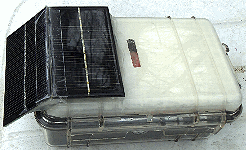 It was our experimental SPOT4 tracker, sat in the garden, on test and sending THREE reports every hour, that
alerted me to the fault with Spot3 on Boat10. It has a far smaller pair of solar panels than that on Boat10.
Look at that waterproof box on the right, holding Spot4. At 0630 this morning, I put a bit of wet rag
over these small panels, and we will see when this Spot4 stops reporting. That should also be a useful guide
to how long we might receive Spot3 reports from Snoopy, after his main autopilot power fails - if it does.
It might be hours, or it might be a day, and enough time to do the best we can to rescue him, while we still
know where he is !
There are other things that Snoopy's latest attempt is telling us, related to our next version of the autopilot, using a better Picaxe computer, GPS, and rudder servo (all discussed above), and these will eventually get reported here.
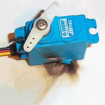 Thursday 26th March:
Don't feel bad, Cesar in Romania, but your suggestion of trying the HS5086 servo did us a big favour:
it reinforced the importance of testing a product before changing the design, based on what is seen
on paper. It will also make us look more seriously, in the long term, into a vane-rudder clutch
based autopilot: but that may take years before someone designs, tests, AND produces the right product.
See when we put this product under 2.5x accelerated 24/7 test above, on Wednesday 4th March.
At about 8pm this evening the house stank of something burning: it still stinks now,
after having the patio door open 2 hours. I calculate this failure, after 22 days, equates to about 2 months
of typical Snoopy autopilot use. i.e. not reliable enough for a trans-Atlantic crossing, where each
critical element should have nearer 12 months or more as a MTBF (Mean Time Between Failures).
I will be happy to connect any servo supplied to me into the same test rig. The trusty Acoms servo
is still running: we will see when that fails. The earlier failure, in the Blog above, gave
the same symptoms. See those scorch marks on the paper it was sat on, and is now stuck on. It's a good job it didn't start a house fire !
Today I also got a small mains 5v supply from Maplins, so we could put a complete autopilot here under 24/7 test, looking for a "frozen autopilot failure". The Acoms servo will probably be moved across, to join the autopilot Picaxe 08M2 computer, BR355 GPS, and Text-To-Speech, that tells us that it is working correcting, giving guidance to Bray Lake, as in our "Pub Tests".
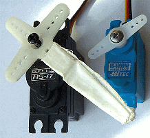 Friday 3rd April 2015:
The Spot4 tracker is STILL running off it's internal batteries. The second Acomms AS-17 servo failed on it's
accelerated 2.5x reliability test. This new one lasted 17 days, equivalent to only 42 days, compared with the earlier,
used one lasting about 30. Another one was started on test. This seems as if the AS-17 product only has a MTBF
in the ballpark of 1 or 2 months: not enough for an Atlantic crossing. We will continue with the AS17 until we find a better
product - with low standimg current. If anyone finds one, with low current ~10mA or less, they are welcome to put it in
our test rig.
Sunday 14th June: The AS-17 servo stopped today, having been running since 4th May (according to desk diary). i.e. approx 6 weeks x 2.5 = 15 weeks / 3.75 months MTBF. New As-17 would have been put on same 24/7 test, but test rig mains PSU failed. Battery tests indicate that the servo had failed, drawing more current (and getting hot). This had probably overloaded the PSU.
Friday 24th July:
AS-17 servo reliability test started again, at 1430, after pouring some Halfords Cycle oil into the lower part of the casing,
in the hope that some might reach the motor brushes. If so, this might make things worse, causing the servo to fail earlier.
However, there is a chance that the oil might have some beneficial effect, such as lubrication or dissipation of heat.
This was after replacing the failed mains USB 5v supply. The new supply caused the Picaxe/Servo to "hunt", so a 5v NiMH battery
was added in parallel. We will see how long this servo test lasts, until something fails !
Saturday 25th July: The servo stopped in less than 24 hours, so it seems the oil made it worse. It was hot, like the others.
 Thursday 3rd September 2015:
GOOD NEWS ON SERVO RELIABILITY ? I'm grateful to Peter, who recently suggested that our failures of servos,
mostly due to overheating, might be due to our 24/7 testing of them at a higher rate of use (2.5x?) than
how the servo is normally used in the boat.
Having looked again at our test program SERVOTST.BAS, I see that we are testing at 5x, not 2.5x. i.e. our guesstimate of the rudder servo lasting 1 or 2 months, should be doubled. Also, this accelerated use maybe, as Peter suggests, be the reason for overheating, and the reliability under normal use might be better. For those interested in the detail: our autopilot logic typically operates the rudder about 10 times per minute, of which about 4 or 5 seconds it is central, then moved to left OR right for 1 or 2 seconds. Our SERVOTST software has been operating the servo as fast as it can: about 24x/minute, with each operation being full left AND full right. Hence my realisation that this is 5x rather than 2.5x normal use. ALSO, under typical use, the rudder will only be moved a small ammount, especially if the boat is going roughly in the correct direction. So this full movement in SERVOTST is a more demanding test.
A new test program SERVOT2.BAS was made that repeats a more realistic pattern of 4 secs centre, 2 secs full left, 4 secs centre, 2 secs full right, etc. Note that the new test still uses full throw left or right. The test rig was started at 1000 today, with two servos connected in parallel: our trusty Acoms AS-17, and the Hitec HS5086. The bad news is that this more realistic testing will take longer to show results: i.e. it will not be until we are well into 2016, that we will see if the reliability is better than we have been calculating ! :-)
27 December 2015:SERVO FAILS ! The Acoms AS1-17 servo failed, in a hot condition yesterday.
We can do the arithmetic in slower time :-)
Meanwhile Snoopy's boat10 remains ready for the next Atlantic Attempt, probably in early 2016. It has a new AS-17 servo.
![]()
![]()
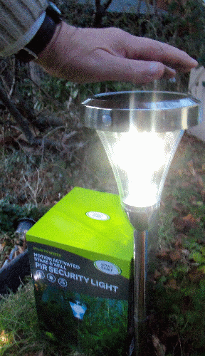 17 February 2016:
We recently found what looks like a better solar garden lamp product for Snoopy's navigation light. It is much brighter, with 9 LED.
Click on the pictures for bigger versions. You will see our tests of solar lamps earlier in this BlogX,
the most recent being 14th March 2014, when the B&Q product was adopted. This has been on Boat 10
used for Atlantic Attempts in 2014 and 2015.
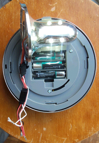 The new "Smart Solar" product, on special offer at £10 from our local Longacres Garden Centre,
is sold boxed as "SOLAR POWERED MOTION ACTIVATED STAKE & WALL PIR SECURITY LIGHT".
The supplier is "SMART GARDEN PRODUCTS LTD" in Abingdon OX14 3PZ and
their web site is
www.sgpuk.com.
This product appears on their web site
Here.
The product grabbed my attention because of the larger solar panel: 5cmx10cm - twice the area of most products.
The 3 cheap Chinese green 600mA NiMH cells were replaced, as normal, by better 2000mAH Maplin cells.
Overnight garden tests look good, and I will soon do more detailed tests, and report here.
18 February 2016:Tests with a meter show the maximum current drawn from the 3xAA (3.6v) supply to be 77mA, when all 9 LED are on. The unmodified device only holds all LED on for 30 seconds, after movement is detected by the PIR. Most of the time, only one LED is on, drawing 13mA. In daylight, all LED are switched off, and batteries are being re-charged.
The unit is easily dismantled by unscrewing three phillips screws. They use a standard Futaba servo connector, between the LED assembly and the rest of the electronics. However, checking voltages on the wires shows that signals are not simple. e.g. 2.8v seen instead of the 3.6v power.
The first important test will probably be to simply replace the lamp on the back of Boat 10, and let it do "The Bray Lake Test" with the solar panel covered, so the LED come on. This would be done near dusk or in darkness, so we can easily see if the motion of the boat is enough to trigger the PIR: we need all 9 LED to be on. This may reveal that we need to disable the PIR. The next step might be to reduce the weight - if we can. It is possible that we switch to this lamp for this year's attempt, but it is more likely it will be used in Boat 11, not expected to be used until 2017.
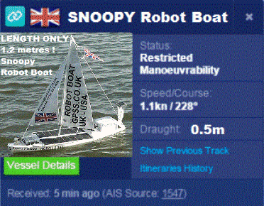
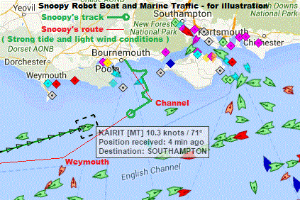 Maybe Snoopy can be made available to all Marinetraffic.com users ?
If so, he might appear as on the left: the picture could include important
information such as his small size !
We are waiting to see if Marinetraffic.com Support can make Snoopy appear, based on the SPOT position reports being forwarded since 15th February. If so, it should not be too difficult to automatically centre the map based on Snoopy's position.
If Marinetraffic.com Support cannot add Snoopy, then we may be able to add our own javascript to achieve the same result. We would probably need to do this anyway, if we want to show extra information such as Snoopy's track over days and weeks, and his intended route.
I have added an experimental page : Snoopy's Marine Traffic for public use. Those wishing to see a more detailed, hidden, page, should email me on my usual robin@gpss.co.uk for the link. I welcome help in things like the experimental Javascript to add graphics such as Snoopy's position and route.
Monday 22nd February: The more detailed "Marine Traffic" page is now public, even if remains well tucked away here. It now has a wider audience, such as the Microtransat List. Recent progress includes using a Mobius camera to make speeded up videos of marine traffic. We have also discovered there are a number of marine traffic sites providing live AIS data.
Monday 29th February:
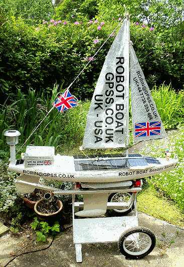 See the Current
Blog
for details, because this BlogX is for experimental work.
The Current Blog is covers Snoopy's preperation for the next attempt.
The autopilot was switched ON at 1020, so we could check everything still works, and how well the solar power stays up, now that the days are getting longer. We don't want to leave the autopilit on for too many weeks, since the servo will eventually wear out: best if it lasts at least a few weeks at sea ! :-) Both duplicated power switches worked OK, with the rudder doing it's corrrect left-right-centre startup, followed by random movements every few seconds, after the GPS starts tracking. Main duplicated 5v power was (6.03,5.16)->5.72v. SPOT was 3.91v. Both SPOT trackers still good, reporting every 20 minutes, on SPOT3 (in boat) and SPOT4 (spare) .
 Monday 7th March:
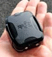
Today I ordered a "
SPOT Trace
" at £78 (see left). It looks as if it could be a much neater solution
than our modified SPOT Messenger + Picaxe Timer. It should arrive this week, and seems to require the usual SPOT service contract.
I also could not resist buying two "
Spy Trackers
" from Shanghai, at only £13.18 each.
They appear to include a GPS, camera, and microphone. At that price, they could be a "throw away" extra to Snoopy's boats.
Pictures or even video from the boat, when in GSM range ?
Tuesday 8th March:
See the
SPOT Trace User Guide for details
such as power consumption. It seems a small solar panel and 4 NiMH cells should be enough to keep the SPOT Trace running,
even if it were reporting position every 5 or 10 minutes. I ordered spare USB cables today, to make an external
solar power supply. This should be capable of being put into a bottle ! :-)
 Wednesday 9th March:
The SPOT Trace arrived today and it did not take long to add it to my account and create this shared page:
SpotT Map
with reports every 5 minutes. A road test, with stops at Jack's, Bray Lake, and Maplins, showed that the product did what was expected.
Before the next step of testing with a solar powered external supply, I needed a suitable test rig to avoid the movement sensor
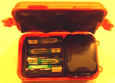
suppressing the 5 minute reports when it is completely stationary. It looks as if I can squeeze it, with 4 x 2000mAH NiMH cells,
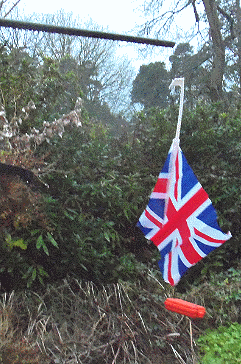
into one of these waterproof boxes. I than hung it up, in front of one of my CCTV cameras, with a flag to catch the wind.
I can add a bird feeder, to cover windless days, but not frosty nights :-) The CCTV should help examine any gaps in reporting.
Meanwhile, I'll assemble a prototype box and we can start some power tests. I'm impressed by the power saving features,
including NOT flashing LEDs - that consume significant power.
2115 update: the "swing rig test" was started at ~1730 and looked promising for about 30 minutes, with reports at "530,536,548,553 and 558".
But then nothing for over 2.5 hours, when I have the tracker box a "good manual swing" - recorded on my CCTV.
Still no report received at 2100. The box was then given "a good shaking", and reports started to come through again.
It will be good if we can increase sensitivity of the movement sensor, or find some work-around.
Thursday 10th March:
"Gentle move" tests look promising: at 0730 no reports had bee made since 2106, but when I gently moved SPOT Trace
down the garden, I got two reports: at 0731 and 0735. I then moved it a few yards away, then immediately back to
same position at 0745: no extra reports. It was moved gently back at 0755: no reports.
There may be report suppression, based on distance travelled, but this is a small threshold
of only tens of metres/yards.
The supplier was not able to solve this problem, of how we can devise a suitable "static" test rig.
However, other tests showed no surprises: external 5v power was supplied through the USB connector,
and the main source of power drain, was - as expected - when the GPS was switched on, drawing ~30mA
for ~30 seconds. The two SPOT transmissions were short spikes. Average consumption is estimated
to be < 5mA, if reporting every 5 minutes. 4 x Maplin 1000mAH AAA NiMH cells were put in.
Hence - if we did devise a suitable rig - I would expect these to last approx 1000/5=200 hours = ~8 days.
If we assume a 6v solar panel got sunlight ~ 2.5 hours --> needs to deliver ~ 50mA.
I ordered three (only one needed) of the
6v 50mA 65x65mm panels
from FirstStopSolar.co.uk - my trusted supplier. This should match that box nicely.
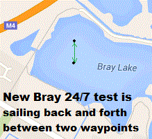 Sunday 13th March:The rig looked too challenging, so instead we will see how the SPOT Trace performs
as intended - on water. Boat 6 can be used for a "Bray Lake Test", but also on 24/7, with two waypoints,
seperated by ~ 100 metres. Lots of scope for bugs in the software change, on the experimental 28X2 version
of the Autopilot. AP28X2.BAS was copied to AP28X2D.BAS and on startup it speaks "12th March 2016".
 Monday 14th March:
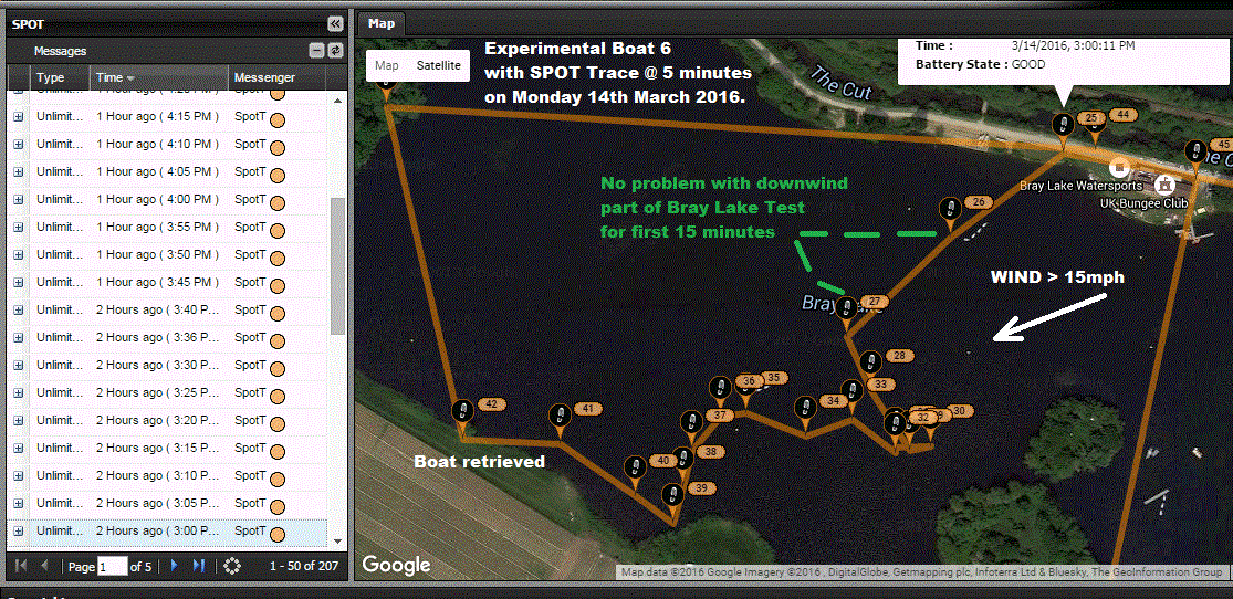
Experimental Boat 6 tried a Bray Lake Test, to checkout the SPOT Trace. Click on either picture for bigger ones.
Wind was from East-North-East at above 15 mph. SPOT Trace worked well, with no positions missed, every 5 minutes,
the launch being at 3pm.
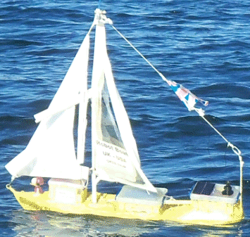 The track does not show how well the boat did in the first 15 minutes,
going through waypoints A, B, and C.
But then the upwind part was too difficult, particularly as
the sails fell apart, due to the old duck tape having lost it's stickyness !
The picture on the right was taken just before the boat drifted to the south bank,
and was retrieved.
Water had got into most of the boxes, so Boat 6 is clearly not in a fit state to test
the new 24/7 Software logic.
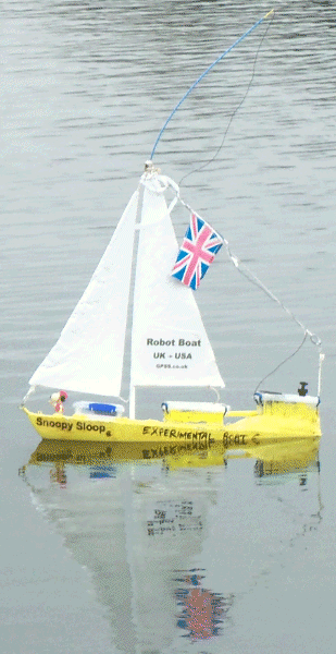 Tuesday 15th March:Another Bray Lake Test in near-calm conditions showed that the SPOT Trace movement sensor
was too insensitive to pick up any positions, in what lasted an hour. It only took 30 minutes, through A,B,C,D
but the last stretch to base was upwind, and shielded by the bank. Wind was 0 to 10(?) mph from the North-North-East.
Earlier in the day, the sails had been re-made using white Solartex. The small box at the front was
replaced by a lower one.
SPOT Trace may be OK at sea, but failure to report position in calm conditions is a major short-coming for 24/7 testing.
Wednesday 16th March:
SPOT Support in USA provided program "console20150806" to change the sensitivity from "Default" to "Lower B".
Another Bray Lake Test took an hour, with no SPOT reports being lost, but wind was not calm:
~15 mph from North East.
Thursday 17th March:
Boat 6 put on 24/7 test before 1207, after completing the Bray Lake Test in 50 minutes.
Wind was a light breeze of ~10mph from ENE. I expect the autopilot battery to go flat tonight,
allowing the boat to drift to the bank,
and we will see how the SPOT Trace behaves. The extra "South 24/7" waypoint, as seen from the footbridge,
lines up with the channel behind the Island.
Earlier reports are suppressed, to make the
SpotT Map
clearer. As the wind drops, we can see "Stop" conditions reported, but without gaps in the 5 minute interval - initially !
The first was seen at 1427, and 7 since then, but by 1800, significant gaps in reporting were appearing.
e.g. 30 minutes between 1653 - 1723.
This
Local Wind Speed Link
from above, in March last year, looks useful - it showing what seems a more true low wind speed than the Met Office site.
e.g. It showed wind speed dropping to below 2mph, seen when June and I visited Bray Lake as it got dark.
The last SPOT Trace report was "STOP 5:33" (p.m.), so the boat had probably drifted to the bank by then.

Friday 18th March:
Daylight revealed the boat where we expected it - how surprising that we did not see it, just before the footbridge.

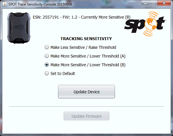
Click on the picture on the right to see the "SPOT Trace Sensitivity Console 20150806" kindly
provided by SPOT Support, with clear instructions for use. Sadly, this has not solved our problem.
CONCLUSION: SPOT Trace may be an easier solution for the Atlantic, but it would be good if we can switch
off the suppression of reports due to the movement sensor not being sensitive enough.
It would then support experimental 24/7 tests under all wind conditions, including very slack or calm.
 Sunday 20th March:
The two GPS Tracker/Cameras arrived yesterday, that I ordered from China on 7th March. All the important functions were tested,
including GPS tracking and sending back pictures. The first bad news was the inaccuracy of the GPS tracking:
position errors of over 800 metres south-west of the true position. This might easily be fixed by the manufacturer,
since it could simply be the GPS needing to be set to WGS84. If this problem were fixed, it opens up a wider range
of applications. Click on the picture for the original ebay advert.
Even if the GPS did not work at all, at that low price, the product is still of use, as a remote camera.
I then tested the second tracker, which I expected to be identical: it was not.
The microphone hole was at the front, beside the camera, and not at the back.
The LED was red, and not white. More importantly, the product would not function:
no reply was given to DWEN GPS position requests. 000 requests for a photo to be stored
resulted in an error message. Both trackers were tested with the same SIM and SD cards.
Despite this, I had given positive feedback to the seller, Chaoling017,
and hope we can help each other. Let us hope these products were not rejected prototypes stolen from a skip :-)
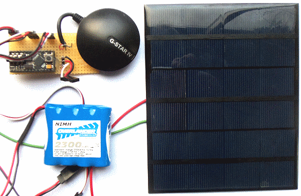 Thursday 7th April: HOW SMALL A BOAT WILL DO IT ? How few of those new solar panels will keep it going ? Just one ?
Inspired by seeing little 2 ft long Micro Magic boats on one of
Eric Wardle's videos I wondered how small a boat might cross the Atlantic.
Our minimum "Marblehead" boat size, of 4 ft / 1.2m, has been driven by the need for sufficient deck space for solar panels. On paper, it seems even
one new panel might keep the autopilot running. Why not give it a test to see how well it does with one panel,
then - if needed - two panels.
Today I prepared the required components to put on Boat 11 for 24/7 testing in my garden, then Bray Lake. One new panel may deliver close to 600mA in full sunlight, ten times the average consumption of the autopilot. The bigger 28X2 Picaxe still only draws 5ma, so we may as well use that, and get all those memory advantages. Note that we are not exploiting those experimental things like a compass and power switching which could reduce power further.
We MIGHT bring our boat down from Marblehead to IOM (International One Metre), but even if we don't, less solar panels means less weight in the wrong place, resulting in what should be a faster boat !
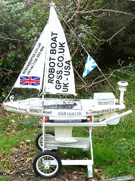 Friday 8th April:Boat 11 with only one new solar panel was put in back garden under 24/7 test, at midday.
with a LOW 2300mA 5v battery, at only 4.81v. We will start with a tough test to see what happens.
The panel will seldom get direct sunlight, and right now, we only get brief patches of sun.
We will see how much the battery voltage climbs during the day and see what it is tomorrow morning.
I expect the autopilot to have stopped, with a flat battery. For those who like numbers, measurements earlier
look promising. Remember the autopilot draws less than 60mA. In bright cloudy conditions, the panel
charges only 47mA into a charged 5.3v battery. However, it pumps 64mA into a low 4.8v battery.
When the sun comes out, this rises to 330mA, of which 330-60 = 270mA should charge the battery.
60mA for 24 hours -> 1440mAH. So 1440/330 -> 4.4 hours of sun needed.
Note that the panel
gives some (smaller) current with any light, so it seems a single panel should have a "fighting chance".
We shall see !
Voltage climbed quickly from 4.81v @1200
to 4.99v @ 1300 but only 5.00v at 1415. It had dropped to 4.92v @ 1700 so it looks as this could be
a duff battery... it was, dropping rapidly to 4.77v@1900, 4.58v@2010 and 3.38v@2105.
A new Overlander 2300mAH battery was put at 5.50v at 2110.
The rudder is now watched by CCTV, so we can see if it fails tonight, which seems unlikely.
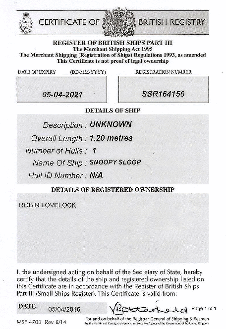 Paperwork arrived today from the UK Maritime and Coastguard Agency with Snoopy Sloop's
Certificate of British Registry. Click on it to enlarge. Snoopy's boat, at 1.2 metres long, must be the smallest
on the UK Small Ships Register. His number SSR164150 is now on the side, in letters
of the prescribed minimum height of 30mm. This was only done so that Snoopy might be granted a MMSI number
discussed in the February words above about AIS.
It looks like Snoopy needs to replace that faded flag :-)
Saturday 10th April: Faded plastic flag replaced, and in it's correct place, near to the top of the mast. Overnight CCTV showed that the 28X2 based Autopilot was still running before the old battery was changed, at only 3.38v ! This morning, in cloudy conditions, that new battery, at 5.5v@2110, was still good at 5.04v@0930. Despite being cloudy, the single new solar panel managed to supply the autopilot and raise the battery voltage to 5.07v@1015. The boat was then moved to a less shady spot, with the sun starting to appear.
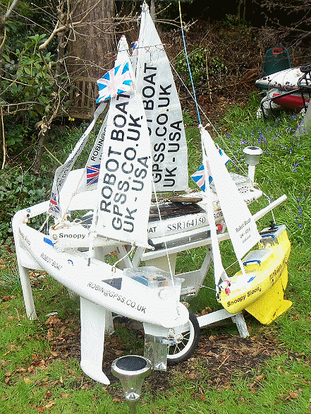 On the right are the three boats: from left to right: Boat 11 (for next year) testing the single solar panel.
The plastic mirror on the rudder and garden light is for the CCTV. Boat 10 (ready for an attempt) has it's SSR number.
Little yellow Boat 6 is always ready to try something new ! :-)
Sunday 10th April:
CCTV watching the rudder on Boat 11 showed the Autopilot ran all night on just one solar panel. 4.79v@0840 climbing to 5.33v@1300 in hazy sunshine.
Monday 11th April:
Autopilot stopped at ~ 6am ( Power < 3.5v ?) seen on CCTV. Voltage was 2.13v@0900 and 2.06v@1015. Still only 2.08v@1235. (Cloudy but
sun starting to appear). I noticed that the
SPOT4
tracker (spare) was not reporting. Power was good at 3.62v but SPOT had switched off (very low voltage in past?).
It was switched on again and is now reporting OK.
LOW POWER AUTOPILOT FAILURE CONDITION ? NO ! :-) I thought we may have stumbled upon a design weakness in the (New 28X2) autopilot that
needs investigation.
Power loss in the early hours resulted in the usual "frozen hard right rudder" condition. However, the voltage remained very low, all day,
at ~2.05v until 1330 - implying that the autopilot had gone into a condition drawing much more than the normal 60mA.
However, this was found to be only 13mA. Reason ? In dull conditions, the single panel produces less current than the Autopilot's 60mA,
so the voltage does not climb above ~ 2v.
The battery was fast charged for 5 minutes then put back on test in Boat 11: 4.93v @ 1725.
We can expect the condition to happen tonight... it did ! Only 1.12v@2130. Sun expected tomorrow.
 Tuesday 12th April:
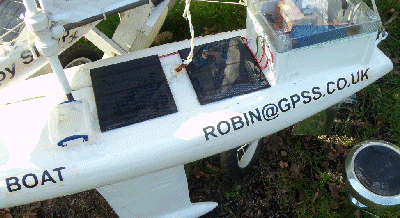
Slow voltage climb, despite bright sun, initially shaded: 2.15v@0815 (shade), 2.04v@0945 (50% panel), 1.98v@1020 ???
50/50 sun charged to 5.13v@1320, 5.26v@1400 ... 5.25v@1600.
Variable 5v PSU showed old Picaxe08M2 Autpilot (used in 2015 and earlier attempts) also (just) runs at 3.6v. AUTOP9TTS uploaded
as online backup. Extra new panels made using diodes such as 1N4007 (0.52v/1A). Second panel (different diodes) added at 1700.
Voltage 5.12v@1700 (shade). It may go flat again tonight, but tomorrow, with two solar panels, it should re-charge better.
Three "2600" batteries were put on "80 ohm resistor test",
drawing over 60mA. If that in Boat 11 looks duff,
we can swap for another, and test that too.
Wednesday 13th April:BAD BATTERIES ? The new "Overlander 2300" was not keeping it's charge (1.08v@0530). Swapped at 0630
for good "2600" at 5.04v. On two solar panels, this climbed to 5.33v by 1045, when one of the panels was deliberately covered.
On just one panel, voltage continued to rise to 5.42v@1430. It became cloudy but was still 5.17v@1800.
We will see how one panel does on a better battery overnight then tomorrow !
An email reply came from OFCOM and, with telephone assistance in filling out the online Form, the radio
Licence
was granted,
1-324825004, with the MMSI 235116575.
Thursday 14th April:The single panel (with a GOOD battery) looks OK: Autopilot ran all night, with 5v power dropping to only
4.96v@0710. 50/50 sunshine charged to 5.12v@1000 and 5.26v@1220. A replacement "Overlander 2300" was put on "80 ohm resistor test".
Friday 15th April:Back to two panels at 1400 because, in overcast conditions, power dropped from 4.61v@0905
to 2.11v@1400. Stopped ~1345 (CCTV). With two panels, overcast, dropped to 2.05v@1500; 2.1v@1640; 1.44v@2000. Sun tomorrow ?
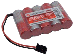 AUTOPILOTS RUN AT 7v OK! I'd ordered three 6v 5 cell R/C Rx packs by mistake, instead of the usual 5v 4 cell packs.
Seemed a good opportunity to see if 7.19v (when fully charged) blew up any of the Autopilot components.
The experimental 28X2 Autopilot with Compass and power switching with AS-17 servo worked OK: no black smoke.
It also drew less than half of the usual 60mA current, as intended. The old (current) Picaxe 08M2 based Autopilot
was also OK at 7.19v. So, in the longer term, we can consider "6v" packs. They should not be overcharged by our 6v
solar panels.
Saturday 16th April:Two panels & bright cloudy: 2.16v@0830. Autopilot restarted (~3.5v?) at 1050 (CCTV).
5.21v@1125; 5.36v@1300; 5.00v@2100; Stopped @2220 (~3.5v?).
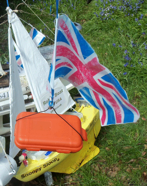
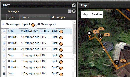 Sunday 17th April:
BETTER SPOT TRACE "Dangle Test" ? Thanks to Andy in Slovakia, I'm now trying a new "dangle test",
to try and overcome the suppression of SPOT Trace reports due to it's movement sensor.
Andy's suggestion was simple: use a longer bit of string ! You will see this discussed
above on 9th March. My longer bit of string, about 4 metres, is hooked over a branch in my back garden.
Click on pictures for bigger ones.
We will see if any more
SpotT
reports are sent, depending on the wind, or if given the occasional nudge ;-)
Two Solar Panel tests continue on Boat 11: Autopilot stopped last night @2220: 2.12v@0910, but with good sun on panels,
was running at 0920. 5.42v@1025; 5.16v@2130.
Monday 18th April: SPOT Trace had stopped, so
a stick was added, from the ground, to "nudge" the SPOT Trace occasional. We now get reports at about 5 per hour, in light wind.
This compares with 12/hour if every 5 minutes. This shows it may be worth making a "timed vibrator", just for use on 24/7 testing
on Bray Lake. Two panel tests of 5v power look good: Autopilot running at 5.02v@0800; 5.31v@0945 in sun. Cloudy: 5.39v@1705.
5.10v@2230.
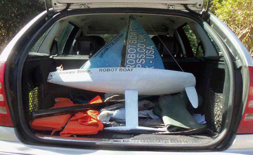 Tuesday 19th April:
There is now a new page:
How we made Snoopy Sloop 12 from Eric's IOM boat.
It will be a "Boat 12 Blog", describing progress on conversion of Eric's second IOM into
Snoopy Sloop 12. Eric's first IOM ended up being Boat 4.
It may even attempt the Atlantic in future years.
SPOT Trace4 stopped, as expected, yesterday. However, when given a vigorous shake at 1055,
it gave a couple of reports. Two panel Autopilot testing looks OK: ran all night.
4.89v@0715; 4.91v@0815; 5.28v@1050.
Wednesday 20th April:
Boat 12, at only 1 metre, certainly fits easier into the back of our car, compared
with the usual 1.2m Marbleheads - even though they use the same 1m high sails.
It looks as if Snoopy Sloop 12 may try his first Bray Lake Test today.
Details will be on that "Boat 12 Blog" page above.
Tests with two solar panels on Boat 11 look good, the Autopilot having run all night:
4.8v@0730; 5.32v@1000 in strong sun. SPOT Trace is now in Boat 12.
 Thursday 21st April:
Yes, Snoopy did his first Bray Lake Test on Boat12 yesterday, and did another today,
completing the course in a record 15.5 minutes. Details are on that "
Boat 12 Blog
" above.
This smaller 1 metre boat weighes 1/3 of my larger 1.2 metre Marblehead boats,
and serves as an example of smaller might be better.
Boat 11 continues to run all night on just two new solar panels. e.g. 5.03v@0630.
Roy visited and had a good idea for a "timed vibrator" to trigger SPOT Trace reports
when 24/7 testing on Bray Lake in calm conditions: a Picaxe timer switching on
a small electric motor with an eccentic weight on the shaft. An old servo
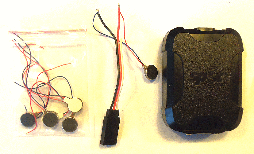
might have what we need. SPOT Trace, operating on only internal AAA NiMH cells,
gave it's first "Low Power Level" email warning today at 1018. The voltage,
checked later in the day was 4.83v. The 4 cells were put on charge.
Friday 22 April:
Thanks to Andy in Slovakia, I've just ordered 6
vibration motors off ebay for experiment. One may be enough to keep SPOT Trace reporting in calm conditions.
The charged AAA NiMH calls (5.82v) were put back into SPOT Trace before 1115.
Boat 11 two solar panel testing still good: ran all night: 5.04v@0640;5.09v@1105; 5.15v@1530; Cloudy.
 Saturday 23rd April:
BETTER JIB SHAPE AFTER SEEING BOAT 12's 15.5 MINUTE BRAY LAKE TEST ? SOLAR POWER: 6v PACK(S) ?
I may make a minor change on the current Boat 10, waiting for the Atlantic Attempt, on where the jib is tied.
It's a minor change and a good excuse to remind myself if the boat can still be put in the car,
for the required Bray Lake Test. e.g. if those rusty quick links still enable the rig to be removed !
Details of that will be reported in the current
Blog soon.
Solar power on Boat 11 failed, as expected, overnight: the Autopilot stopped at 0545 (CCTV), and was 2.07v@0700;
Autopilot restarted ~3.5v@0918 after a few minutes of sun; 5.05v@0950; 5.18v@1040. The usual TWO 5v packs
would probably keep the Autopilot running, after a cloudy day such as yesterday. However, as an experiment, I swapped the
usual 5v 4xAA NiMH pack for a 6v Pack. This was started at 7.01v@1040. We can expect this to drop to between 5.5v and 6v,
even in bright sunshine, because the solar panels only deliver 6v. It's just possible 6v packs run longer on our system.
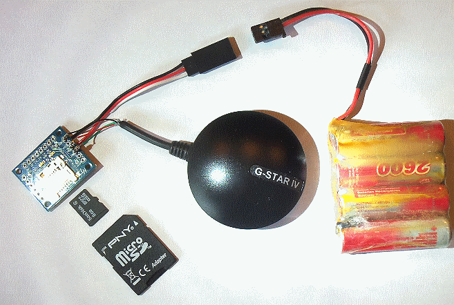
Mr Postman delivered the two
Ardulog
only ordered yesterday. I need to replace that GPS Logger lost on Wednesday from Boat 12.
I soon had one wired up, and with a config.txt on the SD card, as simply explained. However, the garbled data in the resulting log
files, is probably due to the Globalsat BR355-S2 procucing NMEA at 4800, but of opposite polarity signal to that expected.
Hopefully I can find a simple fix, rather than use a different GPS as I did a year or two back.
 Sunday 24th April:
Up at 0230 to give someone a lift to Gatwick, but got some sleep after. The Boat 12 Autopilot, running on a 6v pack, had stopped
after at least 3 hours yesterday. This was noticed in this morning's check: 6.29v@1005. The Picaxe and Servo were OK: giving
a servo waggle on startup, but we did not get the usual 7 second control loop rudder twitch.
At first I thought I'd blown up the BR355-S2 GPS, and checked the CCTV for when it stopped.
However, when put back the usual 5v pack, it all seems to run OK. 5.58v@1010.
We sometimes need to go outside the manufacturer's advice. e.g. how else would we have used SPOT, without different batteries ?
However, this shows lots more testing needed before we switched from 5v to 6v batteries. Don't forget that extra components
to limit voltage are also a source of failure !
 On that Ardulog/BR355 problem noticed yesterday: several options for me:
1) unlikely option of Ardulog firmware being capable of being configured for inverse polarity signal, as it can be for baud rate.
2) use of an invertor circuit: probably just two resistors and a transistor. 3) Use of a different GPS, as I did last time.
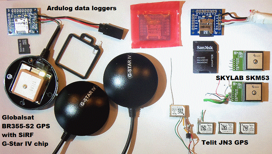
This has prompted me to dig out GPS spares from experimental work done in 2014, and put some of it earlier in the BlogX.
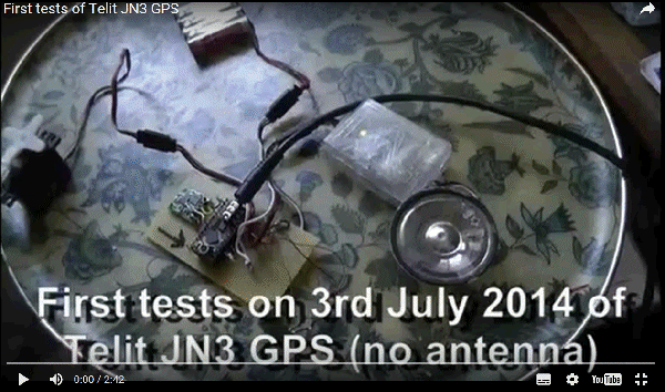
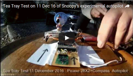
e.g. that video of the "Tea Tray Test" of the Telit JN3 GPS on 3rd July '14. Click on the left picture to play it.
Click on the right picture to see a mixture of recent spares, on the left, and old ones from 2014 on the right.
I immediately recognise the JN3 ! Next job is to test a different GPS with an Ardulog....
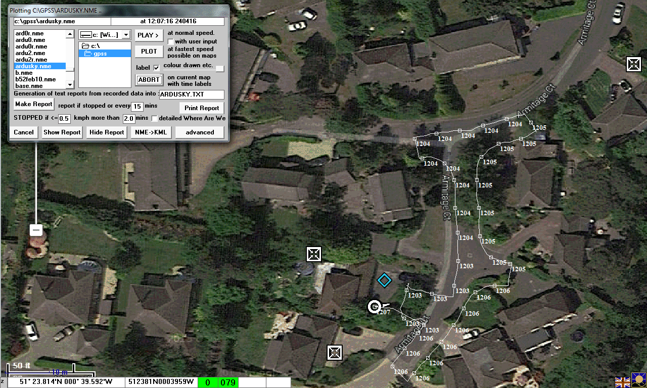 Success ! Click on the plot on the left, to see the detail. It's the plot from a "tea tray test" of the new GPS logger
made from those old spares: an Ardulog with it's SD card, and one of the Skylab SKM53 GPS. It only took a few minutes
to solder, then a few tests leading to the correct config.txt file: this GPS runs at 9600, but with the required polarity signal.
The accuracy looks good enough: that consistent position error, or maybe 3 or 4 metres to the south-east, is to be expected.
My test involved walking along the kerb of the road. The plot was made using the Ctrl-A playback facility in my old GPSS
from my "Download" page. Some errors can also be expected due to calibration of mapping, including that from Google Earth.
It will still be useful if we can get the Ardulog to work with the BR355 GPS adopted for Snoopy's autopilots.
It would enable us to log the actual data used by the Autopilot, during Bray Lake Tests. Don't be confused with
what logger we use for the Atlantic: the I-GotU does a good job, logging GPS positions every 12 minutes for over a year.
The Ardulog GPS logger records position and velocity every second, so we can analyse the boat's detailed movement
during Bray Lake Tests.
Next step is to make a small 4 cell NiMH battery pack, and put the new logger into a suitable waterproof box
- preferably one that floats ! :-)

 Monday 25th April:
I received a good reply from Hobbytronics, my Ardulog supplier, on how to get a BR355 GPS -> Ardulog working. They did not know of any means
of configuring the Ardulog, as there is within a Picaxe or Arduino. However, they did point me to this neat
RS232 Shifter
hardware solution that is worth a try. I've ordered two, delivered 1st Class for just 15.60 GBP. Meanwhile, I have the SKM53->Ardulog
solution above. I could have tried
similar products
from China, at ~ 1 GBP each delivered, suggested by my friend Andy in Slovakia. Or I could have soldered two resistors and a transistor,
just to invert this BR355 TTL signal. However, the "RS232 shifters" might be useful spares in future, for connecting stuff to a PC.
Experimental work continues on use of 6v rather than 5v NiMH packs. This included use of series diodes used in our Boat 10
design, to combine power from duplicated solar supplies. 5.6v zenars could be used to "clamp" the level, but as Roy said,
better to use a regulated supply - or stick with our trusty 5v 4xAA NiMH approach. Boat 11 tests continue, with two panels: 5.19v@1030.
The
vibration motors
arrived today, that I'd ordered last Friday 22nd.
Within minutes I just managed to trigger a SPOT Trace transmission. However, for it to work reliably,
I may need to use several of them, on a suitable platform, held against the SPOT Trace.
If it works reliably, we can then add a timer.
When connected to 5v each draws 110mA.
This would be a stand-alone "test equipment extra", just for 24/7 testing on Bray Lake.
Other related "work" is reported in the
Boat12 Blog
and
Blog pages.
e.g. exloiting the information from the recent Bray Lake Test of Eric's IOM Boat 12.
This 1m boat, at 4kg, weighes a quarter of 1.2m Boat 10, at 16kg. Boat 11 is 11kg.
These "experiments" on Bray Lake are showing how important low weight and sail form can be,
particularly when tacking upwind.
Tuesday 26th April:
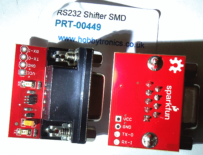
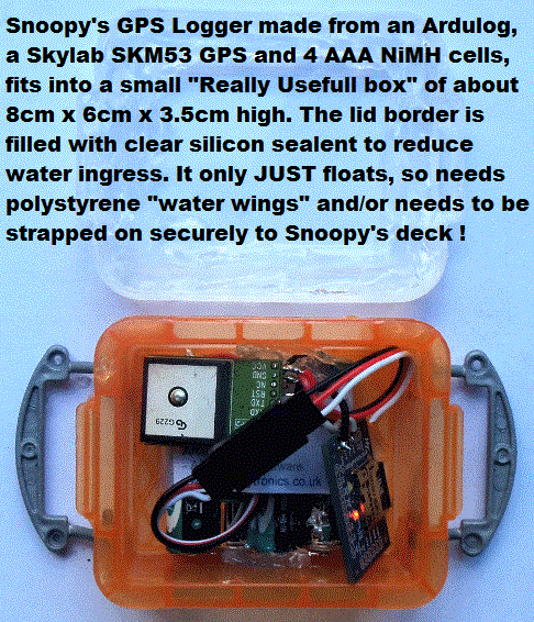 BR355/ARDULOG PROBLEM:
The two RS232 shifters arrived today from Hobbytronics, also my Ardulog supplier. Now I just need to choose which pins to use,
to connect the BR355 GPS through to the Ardulog, and reverse the polarity of the signal.
Click on the pictures to enlarge.
Looking at the underside, on the right, I can solder the four wires needed onto the pins
and not need to use a plug. VCC and GND obviously go to the shared +5v and 0v rails.
I guess the Ardulog signal input could come from TX-0 output, if we put the BR355 output
signal into the correct pin of the 9 way D socket.
It seems it is Pin 3, as seen in the
lower picture, where the green signal wire from the BR355 solders onto the contact
that is wired to pin 3 on the D socket. I was careful, having been warned by a friend that
he never did get this product from Sparkfun to work for this "signal inversion" purpose,
and that he blew at least one up.
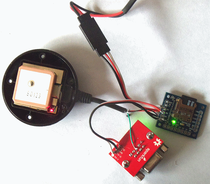 When I applied power it was like a Christmas tree,
with all three products flashing their LEDs. Data was logged, but the result was still
"garbage". So it seems these "RS232 Shifters" do exactly what you might expect:
shift voltage levels, between RS232 and TTL, but not INVERT. Unless someone can
advise me different pins to try ? If not, I can always use a less "clunky" approach:
two resisters and a transistor :-)
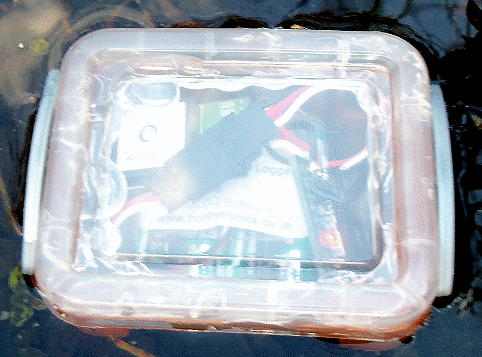
Boat 11 on two solar panels: 5.05v@2215 last night; 4.98v@0825; 5.20v@1000; 5.56v@1400. Other "work" in progress includes the new Ardulog+Slylab GPS logger, now in it's plastic "really useful box" - exactly what was lost in Bray Lake. Tests on my garden pond shows that it only JUST floats, so if water gets in, it WILL go to the bottom. As the picture says: we should add some polystyrene "water wings" and strap it on tightly !
 Wednesday 27th April:
BR355/ARDULOG PROBLEM FIXED: Thanks to Mike at Hobbytronics, my supplier of both Ardulog and
the RS232 Shifter, I now have the Ardulog working with the BR355 GPS. My problem was preceeding
spaces in config.txt setting it to 4800.
Earlier tests this morning made me think the Ardulog firmware
was the problem of it not being able to accept serial data from GPS such as the BR355.
I was wrong: just another example of my making another silly mistake :-)
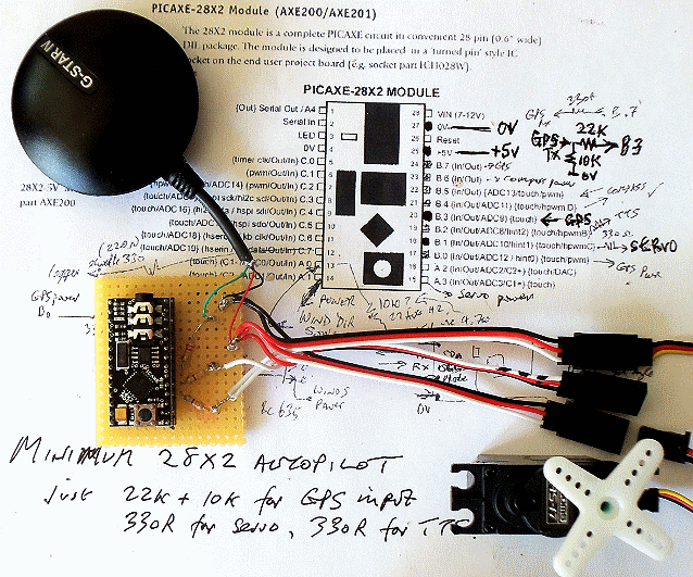
 I've now wired up another Picaxe 28X2 Autopilot for Eric's IOM
Boat 12
so we can try it on other lakes. Click on the picture to read the details,
including my scribbled notes on pin connections, resistor values, etc.
The 28X2 has a lot more memory than the old
08M2 based autopilot Boat 9 used last week, to smash the Bray Lake Test record
- doing the course in 15.5 minutes. This "Minimum 28X2 Autopilot" does not include
the extras that we got working a year or two ago, like power switching, compass, etc.
Just a nice KISS GPS-Only autopilot, like that used for years in our Atlantic attempts,
but with the bigger Picaxe 28X2. I loaded AP28X2d.BAS of the Autopilot Software,
which has all the logic used in the 2015 Attempt 08M2 Picaxe. I'll soon add
more waypoints for other local model boat lakes. The replacement battery for my
Panosonic Camcorder arrived, so I now have a working camcorder for Bray Lake and other places.
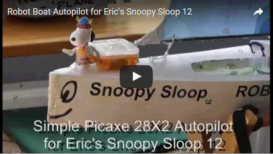
First use was this 1 minute video showing the Autopilot working.
Click on the Youtube video on the right :-)
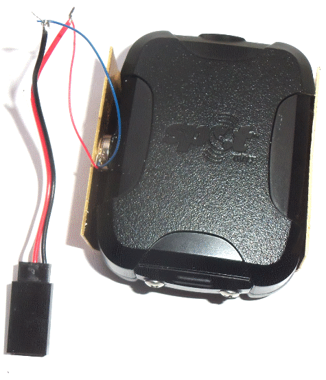
 Thursday 28th April: Spot Trace Vibrator: Here is the simple U shaped bit of brass sheet, cut and bent to make a crade for the SPOT Trace.
One vibration sensor as seen here might be enough to keep SPOT Trace reporting every 5 minutes. After manual tests to
confirm it works, how many vibrators, and the timing ( e.g. 1 vibrator giving 15 seconds of vibration every 4 minutes ? ),
we can consider adding a timer to do it automatically.
Boat12 work included fitting of new Picaxe 28X2 Autopilot, Text-To-Speech box, and neater mounts for GPS Logger and Mobious video camera.
Boat 11 solar power testing continues: ran OK all night;
4.96v@0700; 5.27v@1005 (sun); 5.62v@1610 (cloudy); 5.60v@1800. Progress Meeting in Pub with "Last Of The Summer Wine" Team :-)
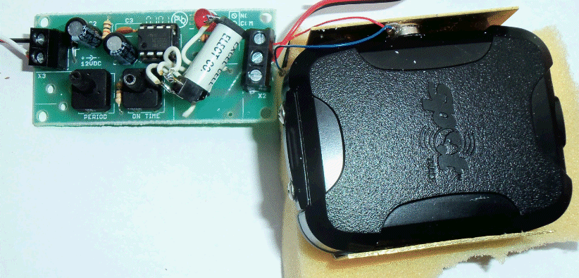 Friday 29th April:
I found this old astable multibrator board in one of my junk boxes, and it is perfect for testing the SPOT Trace Vibrator.
It drives a red LED to show when it switches the reed relay. The power could be shared for the board and any number of
the vibrators.
I set the two pots to maximum delays of about 50 seconds then 7 seconds ON. i.e. roughly 7 seconds vibration every minute.
The brass SPOT Trace cradle is sat on a bit of sponge rubber, so vibration is not helped by the cradle being sat on a hard surface.
If we don't get regular SPOT Trace reports, hopefully every 5 minutes, we can try more than one vibrator, connected in parallel.
Boat 11 solar power tests looking good: ran all night; 5.02v@0730.
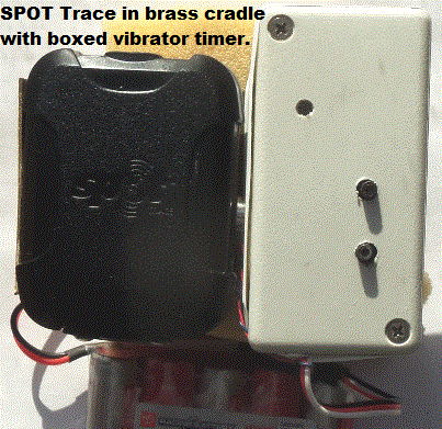 Saturday 30th April:
The SPOT Trace vibrator has worked very well, since it was started yesterday. It seems we get a report every 5 minutes,
although there may sometimes be a few minutes delay. There was an interruption of this vibrator testing, when SPOT Trace
was put in Snoopy's Boat 12 for another experimental Bray Lake Test. Details are in the
Boat 12 Blog.
The Vibrator timer is now in a box, fixed to the brass cradle.
Current measurements on the Timer-Vibrator showed the timer drawing 3mA for it's delay of about 50 secs.
When the vibrator switched on, for about 8 secs, current rose to 132mA. Arithmetic gives an average
of ~ 24mA. i.e. a 2000mAH battery would keep the vibrator going for over 3 days. 24/7 testing
requires a lot longer, so consumption might be reduced by 5x by inceasing the delay 5x
with a suitably large capacitor. I'll now reduce the vibration period, below it's 8 secs,
and see if we can keep SPOT Trace reporting every 5 minutes.
Boat 11 Solar Power testing continues, with it running overnight OK. 5.12v@0930; 5.45v@1200 in sun.
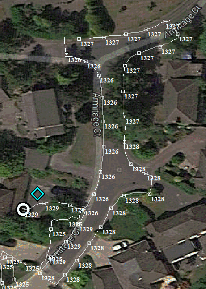 Tuesday 3rd May:
Bray Lake Tests with
Boat12
revealed that the Skylab-Ardulog GPS Logger was not giving good data, due to the Skylab GPS.
A BR355-RS232 Shifter-Ardulog GPS Logger was JUST squeezed into the same box.
The "tea tray test" outside my house seems to give good results, and I expect good results on Bray Lake.
Saturday 7th May:
Important experimental work was done using Boat 12 and is reported in the
Boat 12 Blog.
In brief: eratic sailing, sometimes lasting hours, was seen at Bray Lake and Goldsworth Park.
This was diagnosed as my forgetting to set up the three new BR355 GPS after they arrived from Taiwan.
Here is what I wrote for today, quoting words from earlier in this BlogX:
 Saturday 7th May:
It seems those new BR355-S2 GPS from Taiwan needed a firmware update before I put them into Picaxe 28X2 autopilots or GPS Loggers.
This explains our problems: GPS heading is critical to the GPS-only autopilot steering.
I found this for Saturday 21st March 2015 in my
BlogX ...
QUOTE ... the last few days have been busy, after the launch on Wednesday of Snoopy's
March 2015 attempt on the Atlantic.
However, today I got the time to try a firmware patch sent by the very helpfull Jesse, at Globalsat in USA.
It went very well indeed, only taking a few minutes to install the firmware patch and then test it
- including after powering the updated BR355-S4 off and back on. Now it does what I want - gives random directions
when stationary, and what seem to be accurate direction of movement when moving very slowly, at down to 0.2 knots or less.
I'll do some more "tea-tray" tests, and we will try it out on Bray Lake, in Boat6, soon.
To ensure we do not lose the patch, I'm sure Globalsat will not mind my hosting it here as
[RBPATCH.ZIP].
After testing, it will probably be loaded into all my BR355-S4 here.UNQUOTE.
Guess I should have added, "and any more that I buy in future !" :-)
Cables were soldered up, so that the three GPS could be connected to my desktop PC, via PS/2 Mini DIN on the GPS,
through to a serial port via a 9 way D connector. The "patch" was then applied to all three BR355-S2 GPS, including those
within the GPS logger and the 28X2 based autopilot.
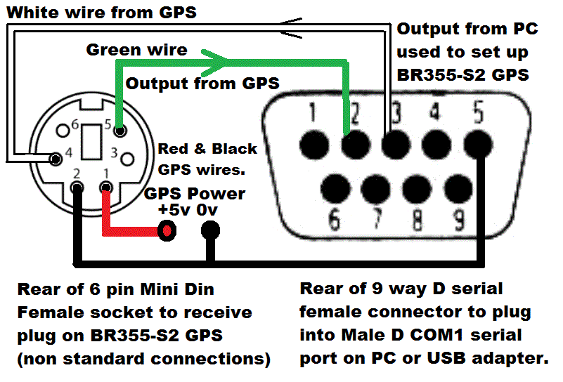 Sunday 8th May:
I thought I should document how I wired up the required connectors, so I could install that patch to the BR355-S2 firmware,
then use SirFDEMO to set up the GPS to the required characteristics. The Globalsat BR355 use industry standard Mini DIN plugs,
but not standard use of the pins ! I hope I've drawn that diagram correctly on the right, after referring to what I wired up
- which worked. The 5v power to the GPS was provided via a Futaba female socket, so I could plug in a standard 5v battery.
The red GPS LED comes on, and flashes when it is tracking. Running SiRFDEMO, downloaded from the SiRF site, will show if
you have wired the green signal wire correctly. If you can change things like the NMEA messages, then the white wire is OK.
More in a moment. If the GPS is wired correctly to the PC, running the patch EXE should finish after a minute or two.
Then SiRFDEMO is used as follows: 1) switch to SiRF mode. 2) Switch off static navigation. 3) Switch to NMEA mode and select
options of 4800 baud, and disable all NMEA messages, such as GGA, VTG, GSV, etc, with only the RMC set to every second.
You should see this in the stream of NMEA data displayed. i.e. only the RMC sentence every second. You should see the
GPS speed and direction, near the end, changing slowly. i.e. not always zero speed and a fixed direction.
e.g. Below is typical GPS data, when static, which does have a zero speed, but random direction: 135.66, 126.94 and 133.90.
$GPRMC,173700.000,A,5123.8165,N,00039.6035,W,0.00,135.66,070516,,,A*79
$GPRMC,173701.000,A,5123.8165,N,00039.6035,W,0.00,126.94,070516,,,A*77
$GPRMC,173702.000,A,5123.8165,N,00039.6035,W,0.00,133.90,070516,,,A*74
The BR355-S2 GPS is now set up nicely for the GPS-Only Autoplot to steer the boat, with maximum direction sensitivity and minimum data to load the Picaxe 28X2 computer.
 Now we can try Boat 12 on Bray Lake again, with the modified 28X2 Autopilot and GPS logger.
Monday 9th May:
SPOT Support emailed me to confirm transfer of SPOT3 air time across to SPOT4, now in Boat 10. So this is good until 19 Jan 2017.
Saturday 14th May:
The SPOT Trace vibrator was fixed (vibration caused a solder wire to break) and tried with three vibrators. Works if 9 secs
of vibration every 1.5 minutes. SPOT Support emailed (again) to see if they can supply a later version of software
used to change the movement detection threshold, the "SPOT Trace Sensitivity Console than 20150806".
This would be a neater solution than adding a vibrator or modifying the SPPT Trace electronics with a soldering iron !
Tuesday 17th May:
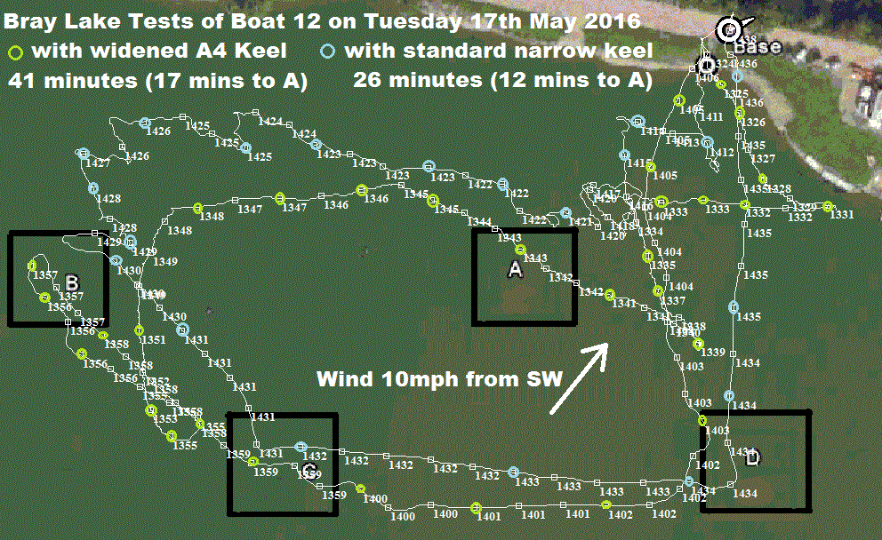
Bray Lake Tests showed that there is no advantage in widening the narrow keel on
Boat 12. Click on the GPS Plots to see the detail.
The single solar panel on Boat 12, might JUST be sufficient for UK latitude, climate, and short winter days. Two panels on Boat 11 (for next year) should be enough, and also provides duplication against failure or seagull poo. A single panel, for a very small boat, might work well enough to keep the autopilot running 90% of the time. Remember : these experiments are for future boats, not Boat 10 ready for this year's attempt.
SPOT Tracker links are:
SPOT4 (in Boat 10
ready for Atlantic)
SPOT3 (DEAD)
, and
SpotT
(in Boat 12 or under test with timed vibrator).
![]()
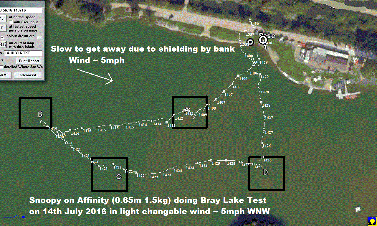 13th July 2016:
This is Snoopy's smallest robot sailing boat so far: Affinity, with very minor modifications. Just 0.65m long (50% of Snoopy Sloop 10),
and 1.5 kg ( 10% ! ), Sailed well on first Bray Lake Test yesterday, but lee helm meant that it did not turn into wind, resulting
in hitting Waypoint C by accident - cutting the mission short. The jib has now been let out, as with all the other boats.
14th July 2016:
Click on the
GPS Plot on the right to enlarge. It shows Affinity doing well, until it got stuck in weed again, a few yards from Base.
This time Robin improvised a longer pole, with a tree branch, avoiding putting £5 into the Bray Lake Watersports drinks kitty :-)
Snoopy (boat 10) remained in the back garden until we got our "weather window".
See Snoopy's 2016 Atlantic Attempt on 20th October 2016.
Snoopy Boat 10 was lost at sea - but no problem - Boat 11 has been waiting in the wings for years ! :-)
![]()
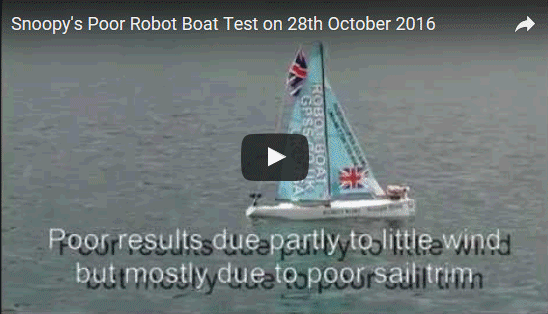 We also have other boats to experiment with...
Here is our Bray Lake Test with Eric's IOM Boat 12 on Friday 28th October 2016,
witnessed by visiting engineer Karen from the States.
This poor result, of Snoopy failing to turn into wind, and landing on the island, was first put down to the slack conditions.
It was not until the Bray Lake Tests of 22nd November, reported in
Blog6,
that it was realised that the sail trim had been all wrong.
Instead of the two sail booms being set at the usual 30 degrees from centre,
the jib was at 10 degrees and the mainsail at 40. i.e. giving too much "lee helm"
for the steering to have sufficient effect.
What a pity Snoopy could not have put on a better show for Karen ! :-)
Saturday 3rd December 2016: Work on Boat 11, for 2017, is reported in "Blog6", including our now having a slightly improved GPS-Only Autopilot, based on the trusty old Picaxe 08M2, but the later version of the Globalsat BR355 GPS - the "S2".
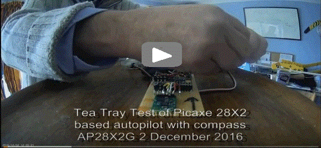 However, this "BlogX" seems the right place to report progress on a new Picaxe 28X2 Autopilot,
that attempts to combine the best features of "GPS-Only" and Compass based steering.
Peter and Dick have been "nagging" Robin for ages on using a compass - and eventually
the penny dropped: no need to scrap the GPS-Only feature of steering based on the GPS based
"Course over Ground", to compensate for tidal drift. The new solution being tested
is a "Hybrid", introducing "Course To Steer" (CTS). However, there are so many things
that could go wrong, including the low level Picaxe 28X2 firmware, that this is
regarded as "experimental" work, until we get it working reliably. Much of the software is based on experiments in 2014 and 2015,
and - hopefully - we will test it sufficiently to use in the 2017 Atlantic Attempt.
 Sunday 4th December 2016:
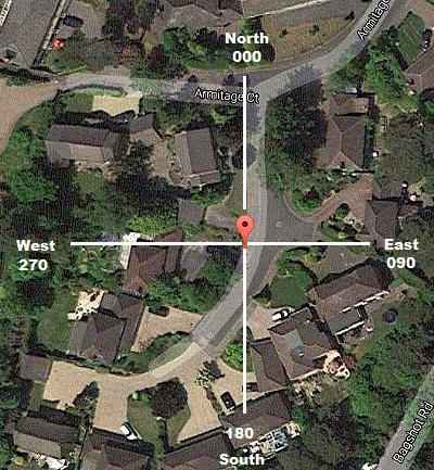
Preperation for more thorough tests of the compass: the panorama below was taken at midday from the
corner of Robin's drive, at 51.39700 -0.65983.
Visual landmarks were chosen
in the primary true directions of North (000), East (090), South (180) and West (270).
The Autopilot software should convert the compass magnetic direction to true, with
an approximation based on longitude. True = Magnetic - ( Lon/4 + 1 ).
Work on AP28X2G.BAS including fixing a bug here and speaking compass true direction for tea tray tests.
The Text-To-Speech voice has been changed from the "deep male" voice to a higher pitched squeaky voice,
more in keeping with little Snoopy the Viking. Some ears may find it easier to understand.
Tomorrow we may try filming a tea tray test.
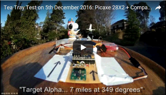
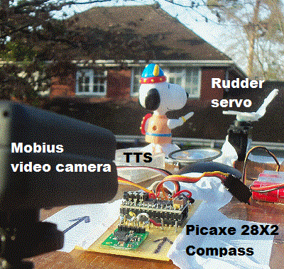 Monday 5th December 2016:
Play the video to hear Snoopy's autopilot new squeaky voice :-)
The software has changes just for testing the compass and steering logic.
e.g. The Course To Steer is replaced by Target direction. I've put AP28X2G.BAS in the usual place, for those helping.
More testing is needed, but we seem to get reliable and consistent boat heading,
and proportional rudder steering towards the waypoint.

![]()

 Wednesday 7th December 2016:
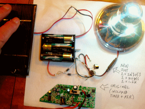
The navigation light for Boat11 will probably be based on the better garden light product.
See details in February.
It could also be placed at the front of the boat: the lamp unit itself behind Snoopy, and the solar
panel just behind.
The 9-LED cluster seems to include resistor components, and is very bright if powered direct
from the 3 x AA NiMH, drawing 170mA, compared with 75mA from the electronics.
The vast number of components should not be needed: a simple threshold detector and power
transistor, should be enough to switch off during daylight hours. I started
a crude test at 1830, watched by my garden CCTV. The LED lamp, battery,
and an old square 13cmx13cm 6v solar panel are connected in parallel.
The product's circular panel and electronics are not used.
If the Maplin cells deliver 2000mAH, that's a good few hours before
the lamp fades. Strong sunlight should charge with ~250mA,
so we will see how badly it does.
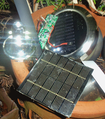 I thought I could make a suitable switch
based on just two diodes, a TIP2955 power transistor, 10R and 1K, but too
bright a light was needed to switch off.
Ordered 10 solar panels for £25.90 from BobDayUp in Shanghai: each 250mA 5v 110mmx69mm. Small enough to fit in several places.
BobDayUp supplied the better main 6v panels we use in Boat 11.
Click on pictures to enlarge.
Thursday 8th December 2016: Lamp was still on at 10am.
I soon got a simpler solution working for the lamp electronics: just two diodes, two 1.2K resisors,
and two 2N3053 PNP transistors. It switches off and on nicely, and was put outside at 1630
to see how it copes in the coming days, with a 130x130mm 250mAH 6v panel.
Roy took a BR355 GPS for his Micromite tests.
Friday 9th December 2016:
CCTV showed Lamp battery had gone flat within a few hours. Properly charged ? Only 2.17v at 0720.
Put on test with another battery at 0830 3.78v. 3.77v at 1035 after trip to Maplins for more
2N3053, AA NiMH cells and new charger.
![]()
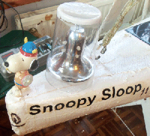
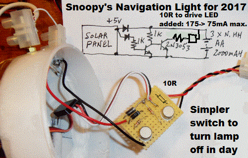
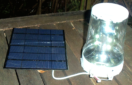 Longacres no longer stock this better solar lamp product, but I have a spare,
and another was assembled for testing, before fitting to Boat11 for 2017.
The 9 LED cluster and conical reflector fit nicely in a plastic pint beer glass,
with room below for the 3xAA NiMH battery pack. Two terminals will allow connection of (any) 5v or 6v solar cells.
The new "Beerglass lamp assembly" was connected to a 6v 500mA solar panel and put outside for test at 1830.
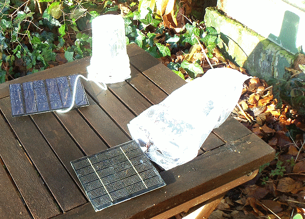
It was joined by the earlier "breadboard version", protected by a polythene bag at 1840. Both were glowing very brightly.
![]() Saturday 10th December 2016:
CCTV showed that both lamps glowed brightly for hours, and were still glowing, less brightly, when daylight made
them switch off, soon after 0730. Tests at 1100 showed that the cloudy sky meant only 5mA charging current,
compared with nearer 500mA in direct bright sunlight. Cloud meant Solar Voltage dropped from 4.33v
to 2.23v by 1420 ! An extra brass bolt was added to allow monitoring of the 3xAA NiMH battery: 3.70v at 1520.
The prototype (bagged) lamp switched on at ~1600, and the beerglass lamp, after at ~1615 - due to a better solar panel ?
i.e. on this cloudy winter day, the lamps switched off for ~8.5 hours.
We will see how the lamp system (mis) behaves.
Saturday 10th December 2016:
CCTV showed that both lamps glowed brightly for hours, and were still glowing, less brightly, when daylight made
them switch off, soon after 0730. Tests at 1100 showed that the cloudy sky meant only 5mA charging current,
compared with nearer 500mA in direct bright sunlight. Cloud meant Solar Voltage dropped from 4.33v
to 2.23v by 1420 ! An extra brass bolt was added to allow monitoring of the 3xAA NiMH battery: 3.70v at 1520.
The prototype (bagged) lamp switched on at ~1600, and the beerglass lamp, after at ~1615 - due to a better solar panel ?
i.e. on this cloudy winter day, the lamps switched off for ~8.5 hours.
We will see how the lamp system (mis) behaves.
![]()
 Sunday 11th December 2016:
Yesterday's overcast conditions meant low lamp power.
The beerglass lamp was fading by 2100, after 6 hours. Today we had sunshine
and the lamps were moved to a sunnier position. The beerglass battery was 3.33v at 0940
and 3.89v by 1350.
Another Tea Tray Test was filmed of our experimental Picaxe 28X2 + Compass Autopilot, using AP28X2G.
The control loop is now about 12 seconds, including a 2 second GPS navigation check, and starting to speak
information such as time, range and direction to the chosen target, and compass heading. Time now includes
seconds, and this is close to that in the Mobius Camera video.
The speech is in parallel with the 10 second rudder servo control loop,
which updates the rudder every 0.5 secs. Steering is based on compass direction:
not yet Course to Steer (CTS) based on GPS direction.
Both lamps on ~1615.
Monday 12th December 2016:
CCTV showed that Both lamps dropped to low brightness by 2100 ( ~ 4 or 5 hours ), so a series 10R resistor was added
to reduce consumption from ~175mA to ~75mA max. - without a noticable lowering of brightness.
Circuit diagram above now updated.
After charging batteries,
both lamps were put outside ( off in daylight ) before 1200. Both switched on by 1600.
 Wednesday 14th December 2016:
Dull day yesterday meant lamps did not stay on long, but today was very sunny. Beerglass was 3.91v@1600,
and both lights came on brightly soon after.
I may make neater Mk2 version based on original lamp cover. Roy, who originally got me to adopt the Picaxe,
years ago, has been doing pioneering work with a MicroMite: already getting it to read the BR355 GPS
and control a servo. The Basic is JUST like the VB2 used in GPSS.EXE from the early 1990s !
I also received two CMPS11 Compass boards. One now with Roy. I did a quick swap with the CMPS10 on a 28X2, but it did not work.
I guess the Devantech CMPS10 and CMPS11 are not completely compatible :-( Better news on the "sticky letters on the sails" front
( in
Blog6
) :
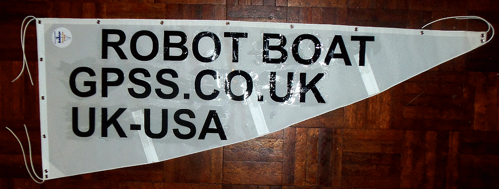
the sample "GPSS.CO.UK", "UK-USA" stickers from Steve at Humberton Signs worked MUCH better,
and I've protected these with clear sealant. I'm about to order more of these better letters,
with a stronger adhesive.
![]()
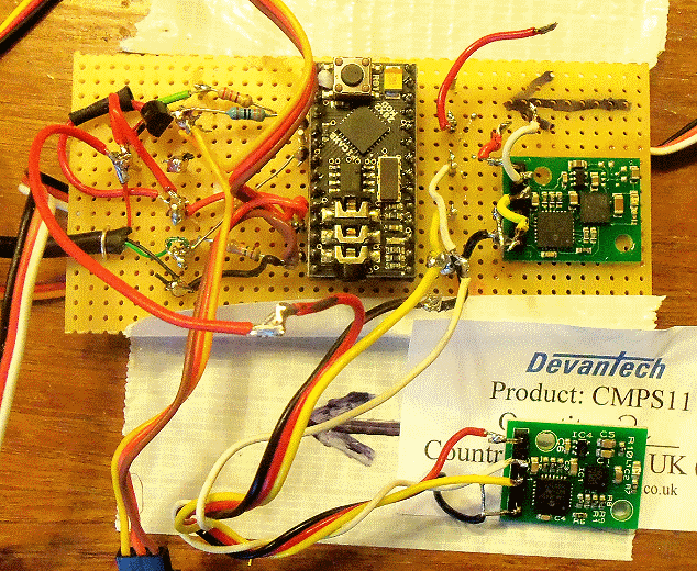 Friday 16th December 2016: Lots of good progress, the most significant being the visit by Phil Boyce of
MicroMite.org, the supplier of the chip, that requires
Basic just like that in Robin's old Microsoft Windows PC GPSS.EXE software. It seems very probable that we
will be collaborating both technically and in some publicity: perhaps starting with a youtube video showing
a race between Picaxe and Micromite steered boats.
There had been one stumbling block: getting the Devantech
CMP11 Compass to work in a low power mode suitable for Microtransat. Chris, from support at
robot-electronics.co.uk
was very helpful in looking at my Picaxe serial I/O statements that work well since 2014 on the old CMPS10,
but don't work on the CMP11. He suggested increasing a delay from 0.1 sec to 0.2 sec - but that didn't help,
even if I increased it to 1.2 seconds. I tried removing the power switching of the compass, which reduces
consumption of GPS-Picaxe-CMP11 from about 150mA to about 35mA - important for our small boat with few solar panels.
That did not help but then I cracked it: powering the CMP11 direct from the 5v supply, rather than from the Picaxe.
I now have a seperate Picaxe test program APCMPS11.BAS should experimental work be needed. However, I have enough
spare 28X2-CMPS10 for our fleet of robot boats. Priority was then to solve Roy's problem that was probably very different:
adding a CMPS11 to a GPS-Micromite-Servo system. He is trying I2C instead of the serial mode - enabled on both
CMPS10 and CMPS11 by the "mode" pin being strapped to 0v. With help from Chris, Roy got the compass CMPS11
to work on his Micromite.
I'm confident we can get a GPS-Micromite-servo+Compass
system working, even if we have to use an old CMPS10.
We will need power switching, to get the power down, but that should be a simple task.
I'm sure lots of you guys out there will want to buy
a MicroMite and CMPS11 to see if you can solve any more problems that surface.
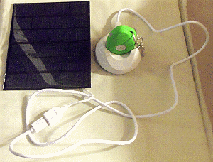 Another bright idea is for a Pocket Pal GPS-Phone-Pendent
to be a permanent fixture on Snoopy's robot boats, powered by a solar panel. Previously I was thinking of it simply
being used as an amusing gimick in demonstrations. e.g. using my (dumb) mobile phone on loud and having
conversations with passing water traffic. "Make way for me, sailing boats have priority !", etc.
More about the Pocket Pal is in our
2016 Xmas Newsletter.
It is from my friends in Shenzhen, is reliable, brilliantly supported, and has amazing capability.
GPS positions are currently reported every 1 minute.
It just so happens that my 30 GBP credit just ran out
after several months of use, including continuous updates to the web site and making 'phone calls in response to the SOS button.
However, it still responds to incoming 'phone calls.
e.g. to listen in and/or shout for help. I tried to top it up, but will visit Tescos. I'll put detail near the top
of my
AVL/Chase page.
5v power is needed if more than 12 hours.
One was put on test last night: it plugs straight into a BobDayUp solar panel. It said it was 89% charged after
10 minutes from being completely flat ( June had left it in her handbag ). It stopped GPS updates at 0236 ( ~ 4.36 hours ),
so maybe it was not fully charged. Also during today, we did not get enough light for the Pocket Pal to start charging.
However, holding it up to our "Games Room" lamp, it lit up. We will see how it does in coming days.
The solar lamp tests continue, but in dull winter conditions, the brighter LED product
only stays on for a few hours. So we may switch back to one of the garden light products already tested.
![]()
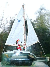
 Sunday 18th December 2016:
Two things happened yesterday that sparked discussion, leading to these careful words on the subject of underwater robot boats.
One was Roy's email with progress on getting the MicroMite to work with the CMPS11 Compass, as well as with GPS and rudder servo.
The other was the BBC Radio and TV news about the
Chinese intercepting an American underwater drone
just before it was recovered by a US warship.
This is all about snooping on each others nuclear and hunter-killer submarines.
One does not need much imagination to realize the vast number of underwater military mobile sensors now operating,
particularly since they can exploit cheap commercial technology.
Any hobby project underwater may not get the same relaxed attitude as for surface water or air robots.
e.g. that
Trans-Atlantic flight by a robot model 'plane
in 2003.
I guess we should steer clear of taking Snoopy underwater.
The discussion did prompt me to find this clip from the 1964 film
Dr Strangelove
.
I fondly remember watching this film, in the City University hall of residence, when I was a student.
It was not long after, working in Holland, that I realised how authentic that political satire black comedy film was.
Many of my surviving retired USAF, RAF, NATO and EASAMS friends will enjoy playing that clip,
now on my
Home
page.
I've been fortunate in my career, unlike some of my
friends, and departed
workmates, never having the "need to know" about military underwater projects. e.g.
Astute
.
I'm happy for it to remain that way.
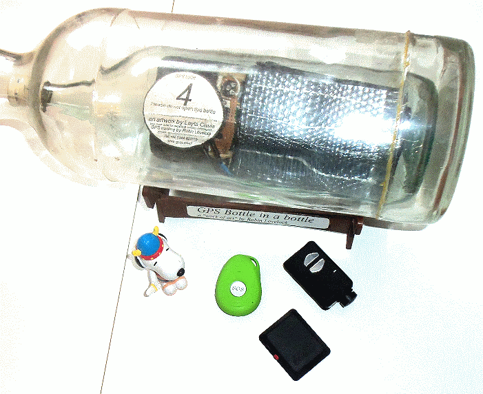 Yesterday, I also had a bright idea which could be fun, require little work, and could be
a source of publicity for guys like Phil:
put a Pocket Pal into a GPS bottle, along with Picaxe or Micromite based autopilot,
small solar panel, and maybe even something like an X009 GPS-phone-camera, as on my
AVL page. Details of contruction are on my "bottle" pages:
click on Snoopy to the left, to visit the BBC GPS Bottle project. Follow the links to the
first one, in 2004, when our GPS bottles were tracked from Ramsgate, along the coast of France and Belgium,
to as far as Den Helder in Holland. Technology has moved on since then.
We have the small magnets to couple servo to rudder, through the glass,
which may mean we would not use a compass. We might use one, with or without sails, to sail down the Thames.
We will get our GPS position reports every minute, can listen in for local sounds, and might even
have Snoopy shout to guys passing - if they can hear him through the glass.
The camera would allow us to get a photo onto a 'phone. Yesterday I spent a princely 25 GBP on
a phone with a camera, and June and I have already tested it's ability to send and receive photos.
If there is anything really interesting happening, we can start and stop video recording:
the SD card in the X009 ( or similar product ) should hold more than a hour of clips.
Or we might use a Mobius camera, if we don't mind waiting to see the video,
like that already shown on these Snoopy pages.
Click on the picture on the right to enlarge. It shows Robin's "Work of Art": a bottle inside a bottle.
If I get enquiries about that "underwater stuff", I will probably answer
as I have to journalists who ask if Snoopy's destination is near the Mayflower in Plymouth, USA:
"You may say that, but I could not possibly comment" :-)
Wednesday 21st December:
Small solar panels arrived and fit nicely in space space on Boat11. Dr Strangelove now important: see end of
2016 Christmas Newsletter.
 Saturday 24th December 2016 ( Christmas Eve ):
Great to be CCd with Peter and Dick's Drone stuff.
I'm on standby for a call from Frimley Park Military Hospital to collect and take Jack home.
Click on that screen image. It's from my
Xmas Newsletter with the latest news.
Thanks Peter for triggering that Dr Strangelove piece. Another old German ex NATO Scientist
sent me this in our Christmas exchange...
"
Thanks for your email! I was glad to hear from you and LOVED your many stories, videos etc. Yes, you are the prototypical mad NATO scientist, so typical for the successful STC scientists of the days before they turned that place into a bureaucratic, bloated Agency. We had some fun, did'nt we.
".
That reminds me of the 1970s prank played on my STC* workmates related to
Snoopy's Windmill Boat page :-)
* STC = SHAPE Technical Centre, now called the NATO Command, Control and Communications Agency (NC3A).
![]()
 Friday 30th December:
Had a nice sleep on the sofa, beside June watching that rather violent Captain America, while she Sudoku
( not SodUtoo ). Earlier we saw Jack getting himself to bed by webcam, with a perfect emergency home care
package in place by Maidenhead SS. Bracknell Forstcare SS take over tomorrow. I just love that abbreviation
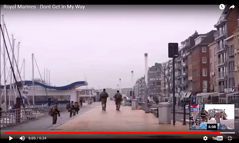
for Social Services. You may like that frame we saw near the end of that Royal Marine recruitment video:
no, not Brighton: wrong lampposts. June saw a Dutch or Flemish sign. Maybe near that bit of Belgian Coast
where that Fishing Boat was based ? :-) Anyway, June's Pocket Pal has been put outside, connected to
that solar panel, to see how it behaves. Most of my spare time is plugging bits of new found video
into the Christmas News video. Tomorrow I should add the reunion of STC friends and dramatic stuff
that interrupted Red Kite filming with dear Travor. Anyone who plays the video may be surprised
by Snoopy's recce flight low over the Sandhurst Royal Military College years ago - with their permission :-)
Plenty of time to move video clips around. Bits can be used by others, according to the need.
So far, it looks like it has been a Great 2016. I look forward to fun with things like the MicroMite
and stunts with Snoopy, etc. Take Care ! :-)
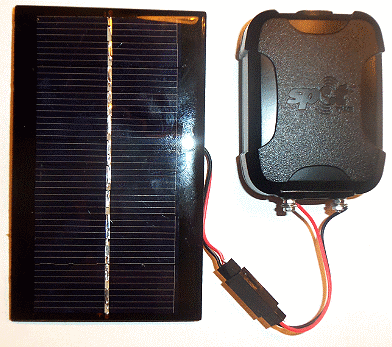
 Monday 9th January 2017:
The SPOT Trace tracking page is public near the top of the
Snoopy
page, where it says,
"
Robin & Snoopy's car is
here".
I noticed last Saturday, that it had stopped, but the battery voltage was 5.08v. It could only be restarted by disconnecting
the batteries then pressing the ON/OFF button. It would be good to know how low the battery voltage must drop, for this to happen.
The simple modification is described in
Blog6
on 19th November. Experimental work is needed by someone, since the SPOT Trace tracker is the most important part
of the whole robot boat system. It is currently set to report every 5 minutes, for test purposes.
Sunday 15th January 2017:
SPOT Trace
here"
is still coping, despite little light on the solar panel, and it giving "low battery" warnings.
The Pocket Pal, also on a small solar panel, is still running some of the time. e.g. until 12:09pm yesterday, but overcast since.
Roger Stollery sent an inspiring video of model sailing boats with outriggers. I may try something with Eric's Boat 12 for fun
- even faster ? :-)
Wednesday 18th January 2017:
I noticed that the 4 x AAA NiMH cells in the SPOT Trace normally reported as battery "Low", so, at risk of black smoke, I swapped
these for 4 x NiMe cells. When fully charged, each give 1.82v, so that would be 7.28v - way above the reccomended 4 x 1.5v Energizer cells.
However, the NiMe cells were not fully charged, and the solar panel should not raise voltage above 6v. It was switched on at 2030
reading 6.49v and reporting as "Good". We will see how they behave. Normally, with NiMH cells, I get a power low warning email during
a run out in the car.
Friday 20th January 2017:
Progress on new rig on Boat 11 is reported in
Blog6
.
The Ni-Me cells in the
SPOT Trace
were replaced by new ones from Maplins at Maidenhead. The "LOW" in position reports
now appear as "GOOD".
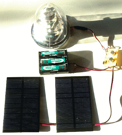
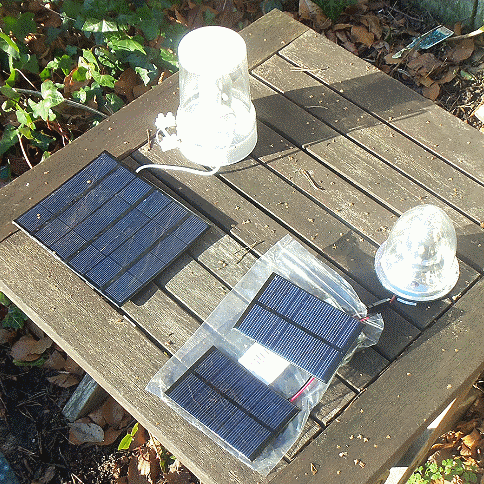 Saturday 21st January 2017:
Click on the pictures to enlarge.
A "Mk2" version of the solar powered navigation light for Boat 11 was made, but this time using an inverted plastic wine glass,
instead of the larger beer glass. The reflector above was discarded, in favour of a smaller size. The electronics were put together,
using the pictures in the December 2016 notes above. This was put outside in the sun, to confirm that it works OK, with
a pair of solar panels, wired in parallel, and chosen to fit on the deck, fore and aft of where the jib is tied.
So far the solar panels switch on at about 1700, glow brightly for a few hours, gradually dimming, before it gets light again at about 0700.
i.e. about 12 hour operation during UK long winter nights. After testing, this new lamp, with it's two solar panels,
will be glued onto the deck of Boat 11, using white silicon sealant. The Futaba plug and socket will be replaced by soldered joints.
![]()
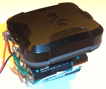 The SPOT Trace solution now being tested for Boat 11 is the same one described earlier, with the four internal AAA Ni-Me cells
providing typically 6.38v. I decided to try five AA Maplin 2500 mAH Ni-MH cells, in parallel. giving 6.36v before these
were connected in parallel - no smoke seen ! The two sticky velkro patches, supplied with Trace, sticks it to the top of the NiMH pack.
This simple and small solution can easily be popped into Boat 11 or my car, for testing. At 1810, SPOT Trace voltage was 6.35v.
Click on the picture to enlarge.
![]()
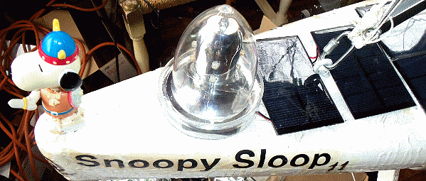
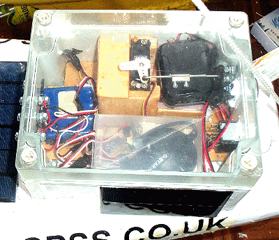 Monday 23rd January 2017:
Click on the pictures to enlarge: they show the final Boat 11 Navigation Light system,
before glueing it to the deck with white silicon sealant. The upside-down plastic wine glass
is mounted on the sawn off top of the beer glass, to surround the 3 x AA NiMH cells and electronics.
CCTV showed the light still glowing faintly after 12 hours on.
On the right you see where the SPOT Trace sits in the waterproof box, with the dedicated
small solar panel on the side, facing a low sun when travelling westward.
![]()
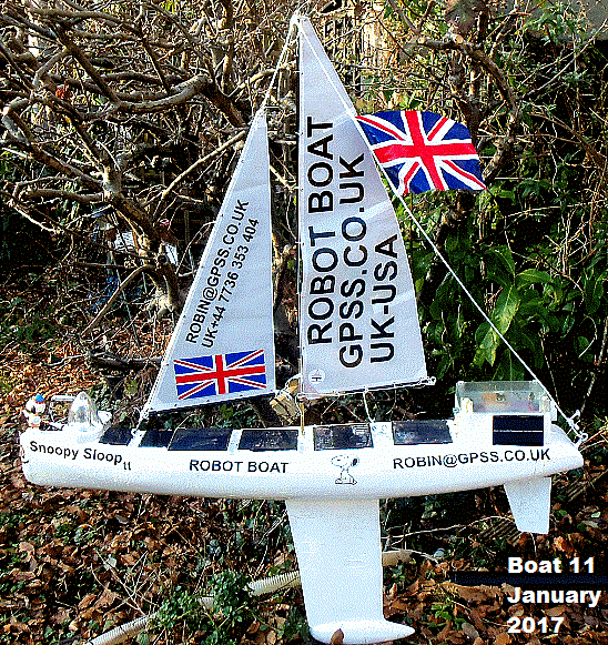
 Friday 3rd February 2017:
The work on things like the navigation light were incorporated in Boat 11, now ready for Bray Lake Tests,
and are reported in
Blog6
.
Boat 11 tests will use the old Picaxe 08M2 Autopilot, and start with checking the "sailing balance".
However, while the weather is rotten, we can work indoors on other things :-)
The main task now might be classed as "experimental": work on the Autopilot, following on from where we were before Christmas: look for this picture above. I have three types of Autopilot planned, each taking over if it is sufficiently well tested:
See further down: or a free iPAQ based one, within GPSSppc, for anywhere in the World collaborating with Team-Joker ? Today I removed that CMP11 Compass, and made a minor update to the software AP28X2G.BAS ready for tests of (2) above.
![]()
 Wednesday 8th February 2017:
This little 1.5 minute video shows a simple way of monitoring a servo signal, using a Picaxe 28X2, to feed back
into Terry's PC based sailing simulator. Thanks Roy for tips including using pulse width. The simulator is intended
to simulate the effect of wind and other forces on Snoopy's boat and generate simulated GPS data into one of Snoopy's
real autopilots. Feeding the rudder servo position back permits it to be a complete, closed loop simulation.
Friday 10th February 2017:
I made good progress yesterday, with Phil and Roy's help, on the MicroMite. See the new page:
Snoopy's MicroMite Autopilot
Great Brainstorm today with Terry. We need to get a cheap Win7 32 BIT PC like I have in the lounge, into his hands !
More news and free mapping expected soon here in coming days, and on Robin's download page. e.g. the mapping for Microtransat simulation.
.
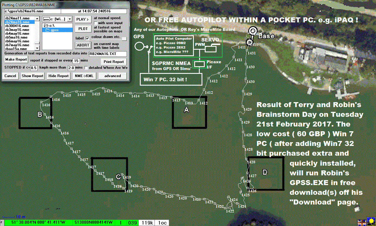
 Sunday 5th March 2017 :
0200z - words in uploaded "Team-Joker Engineer's Video" say....
45 minutes of uncut video showing most of a perfect MicroMite Tea Tray Test through Maidenhead to a suitable spot for future Snoopy River Thames Tests, in Borne End, near the (Mutiny on ?) The Bounty pub. You can see where, using the "Robin and Snoopy's Car" (Spot Trace) link, at the top of the Snoopy page. This video for Engineers then has clips of the Autopilot working at home, together with rapid progress with building Robin's first Sailing Saucer. This is expected to be ready for test this coming week. Interruptions like Samantha's Birthday on 6th March, may delay progress. Conclusions will appear in Snoopy's pages - probably early on Sunday 5th March. The MicroMite Autopilot's BR355-S2 GPS needed the setup process, which took less than 5 minutes, and is documented in www.gpss.co.uk/rb08to10.htm . A trivial software change was seen, that will reject GPS data based on the $GPRMC .V, data, and Waypoint logic can follow quickly. A completed Sailing Saucer can be immediately tested with radio control amd/or a Picaxe Autopilot - probably will go straight for the Picaxe Autopilot - already being put in the box.
Message for Aleksey, if he sees this, or someone tells him. That Windmill Boat was probably invented independently by others. I don't think where I worked allowed that secret "work" to leak :-) I hope you like the video, and will "Reply All" to your nice email later today, Sunday.
After finishing this, I must creep back upstairs to bed, being careful not to be attacked by Michelles horrible cats that were here last Christmas ! :-)
Robin
www.gpss.co.uk
~0200z 5 March 2017
0520z update to the "Snoopy's Team Joker.." Youtube video "Forum" :
Hi Aleksey, Gennady, in Russia, and my other friends around the World, including our extended Team-Joker. This "Team Joker's Sailing Saucer and Snoopy's Robot boat" is the best Youtube video to use as a Forum. The link to this is: https://www.youtube.com/watch?v=4ZR6KL64rBo
Later today, Sunday 5th March 2017, after I have had some more sleep, and obeyed any instructions from my wife, June, I will update my "Snoopy" pages with things like this link, and also the latest news.
All should do a quick check on my "Home" page www.gpss.co.uk to see if anything has changed. Bookmark those different hostings of my "Home" near the bottom. Then if www.gpss.co.uk fails, you should still be able to see my pages.
The important page is then "Holiday" - maybe with other important pages, like "Grumpy", "Bigger Picture", "Radio" ( for Radio Hams ), or whatever interests you.
Right now, this latest news on experimental robot boat work, belongs in "BlogX", and progress on Snoopy's Boat 11 for the 2017 Atlantic Attempt ( maybe in July, or later, after holidays, politics, and LOTS of testing on Bray Lake, and elsewhere, we will do the launch, from the same place. Waiting for a good "Weather Window" may make it later in the year - maybe into the Autumn.
 NOW TODAY'S NEWS: It's in the later video "... for Engineers .." video, uploaded today at 01:14 - before I crept back to bed quietly - which I will do again soon. I will try and get back to sleep, despite my wife's loud snoring. I can write anything I like on Youtube or my web pages, because she does not read them - like many of my friends. Some are not on the Internet at all, but I can print pictures, or burn DVD, to let them share the fun.
The news is about that excellent MicroMite Tea Tray Test to a pub near the Thames, and fast progress on my first Sailing Saucer, that MAY be finished today. Thanks Aleksey ! :-)
As always everyone, decide if best when to use this Youtube video as a forum, or direct email, "Reply All", just to me, Robin Lovelock ( "Contact" page of www.gpss.co.uk ) or to whom you feel should know.
Love and Strength to all :-)
Robin
www.gpss.co.uk
2311z update. This will end up on the "Family" page, but it shows how I spent the day. 11:11pm Spookey Eh ? :-)
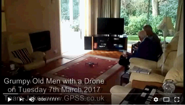 Monday 6th March 2017:
Samantha's Birthday and the women have planned a shopping tip to the Westfield Shopping Mall, near UCL, London. I got 8+ hours solid sleep,
so was up to tidy up some of these pages, and reply to John's email ( gave more detail, for those interested ). I may even have time for
a MicroMite Autopi9lot software update, and a Tea Tray Test up to Richmond Rail Sation. It all depends when the women get up :-)
Tuesday 7th March 2017:
Another 0222z Wake up call: creep down to update "BlogX" with things like my Pocket Pal KML file for those who want to see where
we went yesterday on Google Earth. The file is now in
06MAR17.KML
and you can enlarge the sample screen image by clicking on it.
1030z Update
Progress on the MicroMite Autopilot progressing, as expected, rapidly, because of the similarity with GPSSppc on Pocket PC and all before it, back to the 1960s.
Pub Grub takes priority today, with Stuart, Richard, Roy, Dick, and possibly Michelle, before she and the cats are put down - sorry Freudian slip - put on the train
back to Coventry.
Wednesday 8th March 2017:
Here is what we did yesterday with a Drone, including clearing duckweed for the Sailing Saucer :-)
Friday 10th March 2017: Progress happening rapidly in several connected areas, and the appropriate pages will be updated with pictures and videos soon. e.g. MicroMite AutoPilot progressing rapidly, including coping with a Globalsat BR355-S2 that needs it's settings reset; delivery of four 3G GPS Cameras direct from Sophie at Long-Boom, the same as Jack saw on Kim's dog Kaiser. A bit like a Pocket Pal, but with a camera too ? Sailing Saucer Mk1 almost ready to test with radio control, somewhere like Bray Lake. Then - simply replace radio control receiver by a Snoopy Autopilot; Aleksey, discussing Sailing Saucer Mk2 ( wind vane controlled ), mentions a clutch. He was reading my mind - but my clutch, enables us to dispense stepper motor or 360 degree servo. Discussed years ago, but in short: the clutch normally locks the wind vane shaft to the boat. However, occasionally, the Autopilot can: release the clutch, switch on the power-hungry GPS, any compass, and servo, steer the boat until going in the right direction, towards it's waypoint; the vane will swing downwind. The clutch is then clamped, and the computer switches off those devices, continueing on wind vane steering - until the next navigation check :-) Time to pick up my sandwiches and pop around to Jack's, to give him his mobile 'phone, and have a natter - maybe some tips, like that one about The Peace Rose :-)
Why so verbose and rambling ? Journalists sometime make good use of such rubbish - see AsOnTV page ;-)
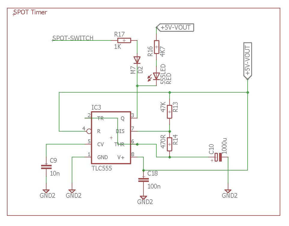
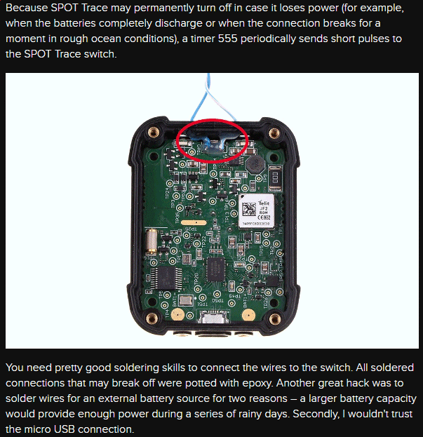 Monday 17th April:
Blog6 reports the problem with SPOT Trace switching itself off when 6v power drops
below some unknown threshold.
I'm indepted to Andrej (Andy) in Bratislava for advice, including about SPOT Trace. I've taken the liberty of repeating some of the advice, including his link explaing use of a 555 timer to keep the SPOT Trace on.
I asked about the 555 Timer and he sent the diagram and this: : "One leg of the switch is connected to the ground, the other one to SPOT-SWITCH label. You can measure with a multimeter which leg of the switch is connected to the ground plane. Use the TLC555 version of the 555 timer because it has only 200-250 uA @ 5V power consumption. http://www.ti.com/product/TLC555 NE555 has much greater power consumption".
Click on Andy's pictures to enlarge.
![]()
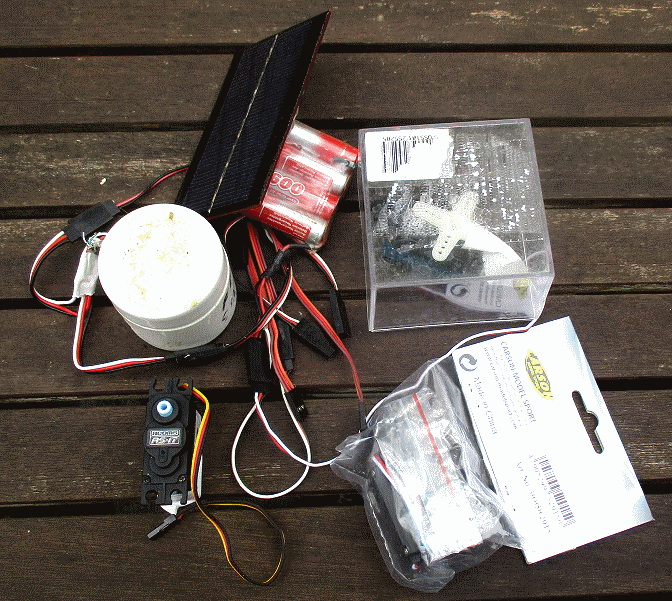 Friday 7th July 2017:
Peter suggested a servo that might be a suitable replacement of the Acoms AS-17 that Snoopy's boats have used for years.
Sadly, Acoms no longer make servos, but I have started testing the Carson-Model Sport Art No 50 050 2015 made in China.
I put one on 24/7 test on the Picaxe 08M based test rig that moves the rudder servo every 7 seconds: left or right,
then back to centre. Typical tests have lasted two or three months, before an AS17 failed. i.e. MTBF 60 to 90 days.
The test was started before 1900 on Wednesday 5th. i.e. now nearly 48 hours and OK.
Monday 10th July update:
A similar, cheaper, unbranded servo from Rooktronics, joined it on Saturday 8th: both still OK.
Peter is checking out a small worm drive based unit that could a better rudder servo solution, giving higher reliability.
Andy has suggested this approach. It would be great if a small board were available, to make the unit plug compatible
with Futaba servos. Click on the pictures to enlarge, play video, or get more details. e.g. that Yagi antenna.
Friday 7th July 2017: Peter's video of his tests of a digital radio link is now below.
Monday 10th:
There has been discussion on better aerials for Peter's link. e.g. a yagi for Rx ?
Wednesday 12th July 2017:
Blog6
mentions 'version "Oscar" AP28X2O.BAS put into Boats 11 & 12 for Bray Lake Test. Includes more SERTXD - see BlogX'.
SERTXD is the Picaxe serial output to PC Terminal, via the Jack Plug on the 28X2 ( and 08M2 ), used for program load
and program monitoring when connected to a PC. Maybe devices like Peter's digital transmitter could have a suitable
jack plug to take this data at 9600 baud ? Or could easily plug an Ardulog ( as used in our GPS Logger ).
If a complete GPS $GPRMC sentence could be output too, GPSS or any map tracking could be added to the receiver on shore.
![]()

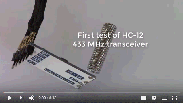
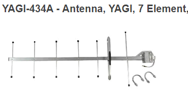
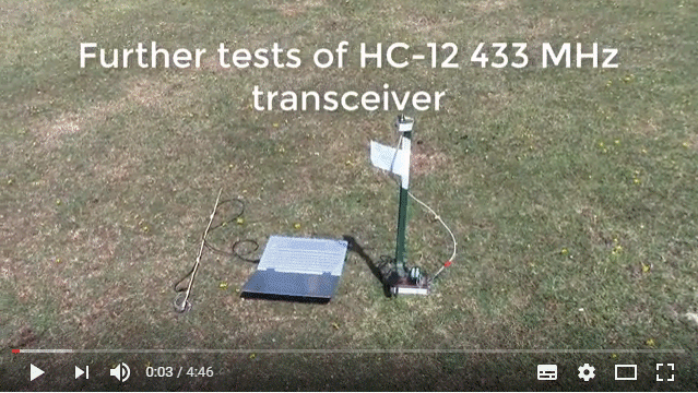
![]()

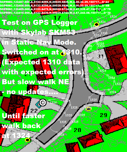 Saturday 15th July 2017:
To the left is the GPS Logger discussed above on 25th April 2015.
This gave problems on Thursday 13th July 2017, described in
RBBLOG6
: not updating lat/lon positions at slow speed,
probably due to a "Static Nav" mode.
Click on the map on the right, to see the results of my test today that confirmed this problem. The GPS data is in AC150717.NME - just the $GPSRMC sentences. ONLYRMC.EXE is used to remove the other unwanted NMEA sentences, after copying from the ArduLog SD card.
I don't have the time to fix this - by changing the GPS, or maybe running SIRFDEMO to switch off Static Nav. HOWEVER, I see that I do have a spare Ardulog module and Skylab SKM53, for any local friends who want to try their skills with a soldering iron, then go up the GPS learning curve. Meanwhile I'll manage with the other GPS Logger that works, recording GPS positions every second, during Bray Lake Tests.
![]()
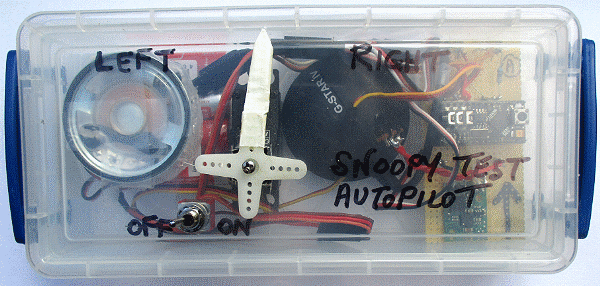
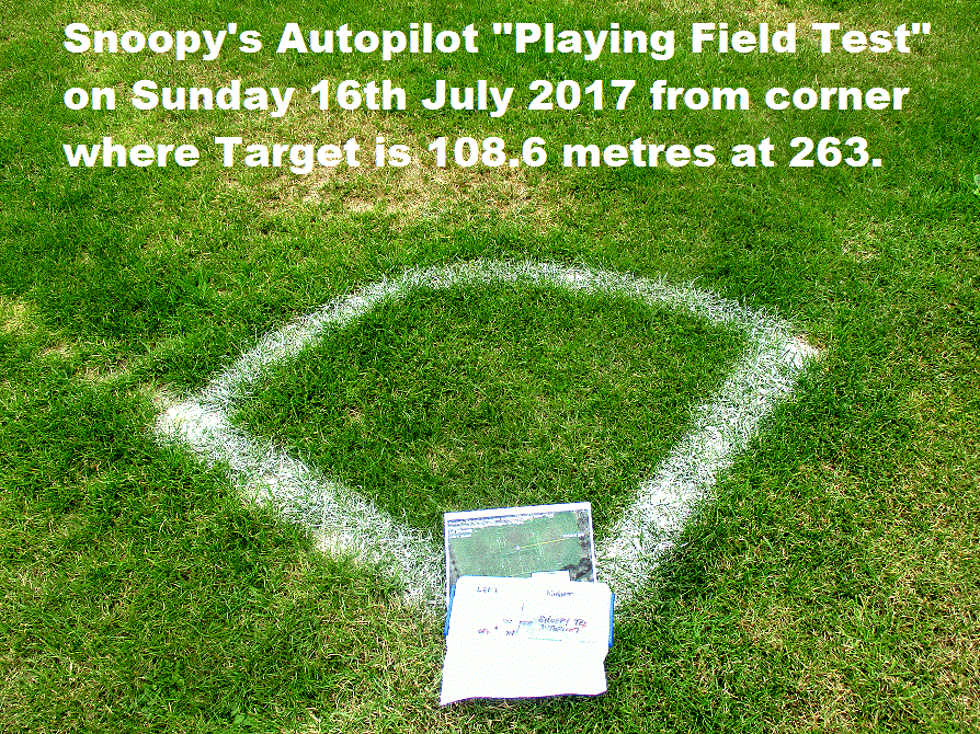
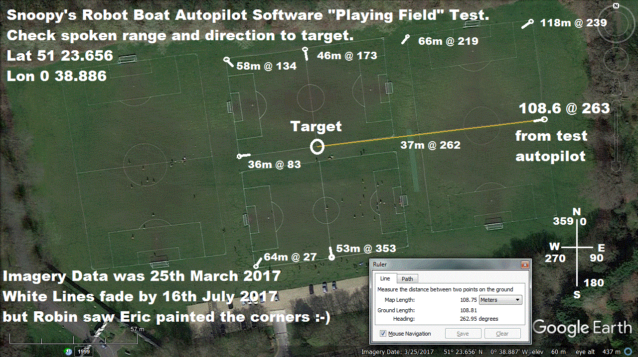 Sunday 16th July 2017:
Click on the pictures to the right to see a new "Playing Field Test" programmed into version "PaPa" (AP28X2P.BAS) mentioned in
Blog6
, and to assist exposing spoken range errors, heard at Bray Lake.
The test worked: spoken direction was bang-on: "263", but range spoke "16 metres" instead of about 109.
Luckily spoken range is only used to assist testing - but it would be good to be correct !
This type of test would be easier if playing field white lines did not need re-painting so often !
After several sessions on the Home PC, then tests at Charters, we now have the software speaking
range to 3 metre or better accuracy, at all the test points. Ready for Bray Lake ! :-)
Wednesday 19th July 2017:
FAILURE of the unbranded Rooktronics servo after 11 days. The Carson one is still running. See 8th July above.

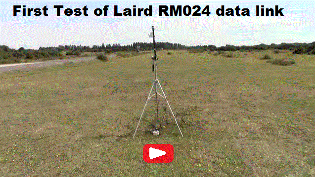 Thursday 20th July 2017:
Peter sent this video showing his first tests in the New Forest of the Laird RM024 digital comms modules.
As it happens, Peter's tests coincided with a Birthday Treat Trip into the New Forest for June, and two of our daughters.
Here is a donkey stallion we met, and another Robin who insisted on sharing a bench at Furzey Gardens.
June then wanted to go south, to sunbathe on the seaweed beach at Lepe Country Park, where
BBC GPS Bottle
"Flashing Fred"
had come ashore years ago. After that, she wanted to try Boscombe Pier, and Robin checked out Snoopy's launch groin:
looks like we need a better launch spot - or use of waders ! Click on pictures to enlarge.
Friday 21st July 2017:
The
Two Robin's
photo is now replaced by the 2 minute Sunninghill CB Range Test video above.

 Sunday 23rd July 2017:
Good News: Two more Globalsat BR355-S4 arrived from Taiwan within 7 days of order.
Bad News: We need a work-around for the problem with the
Ardulog
-
Skylab SKM53 GPS
based Logger, used for Bray Lake Tests, and record the GPS track every 1 second.
See 15th July above.
The problem seems to relate to the polarity of the serial signal - not a problem with
using these GPS with a Picaxe computer ( I just use the correct SERIN statement ).
The solution might be a signal inverter.
I've not been able to get the Ardulog to record good BR355-S4 GPS data at 4800 or 9600.
I've not been able to use SIRFDEMO to handle the Skylab GPS and switch Static Navigation Mode off.
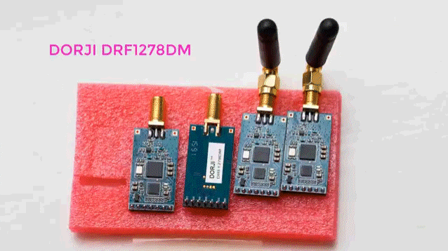
 Thursday 27th July 2017:
Some more time was spent on our problem, discussed above, of the Accoms AS17 rudder servo not being available.
The AS17 was chosen years ago because of the low static current - just 5.1 mA from the 5v supply.
Today I went into Mantua Models and came away with two Etronix ES030 3.0kg Analogue STD Waterproof servo
at £8.50 each. One is now on 24/7 test, at 1700, replacing the unbranded servo which is unreliable
(two failed within 6 days, compared with the typical 2 or 3 months for the AS17). Static current
(with or without a "centre" servo signal) for all servos tested was in the same 6 mA ballpark.
This obviously spikes to a brief 100 or 200mA when the servo moves. AS17 5.1mA; Carson 6.2mA; Unbranded 6mA;
Etronix ES03 6.2mA; Alturn AAS700 6.5mA; Newpower XL16HM Miniservo 6.9mA.
Conclusion: < 7mA from 5v is a reasonable requirement of our new rudder servo.
Sunday 30th July 2017:
A video Peter's New Forest Range Test of digital comms is now above. Click on pictures to enlarge or and/or play.
 Monday 7th August 2017:
I've just ordered another four of these cheap FM bugs, at less than £3 each, delivered from China. This was after
a quick job of soldering three wires: 9v power in, and antenna out. One worked well, and the other gave a weak signal,
so was scrapped. The good one gave a range of over 100 metres from inside the house, to a hand held transistor radio.
This was with just a metre of wire as an aerial. I then made up the box you see below, with an on/off switch,
and two telecopic aerials: each can extend to 67cm which is in the ballpark of 1/4 wavelength, 79cm, for the frequency
of about 95 MHz. It drew about 20mA from 9.96v. ie. a power of approx. 200mW. Two options are possible:
1) extend both antenna to provide a dipole, mounting somewhere such as the mast. 2) extend only the top one,
and push the closed bottom antenna into a brass tube, at the back of the boat, connected to the common 0v power
and into the water as the "ground plane". Quality of sound from Snoopy's text to speech was good and legible.
Tuesday 8th August 2017:
The above can now easily be mounted at the back of Boat11 or Boat12, by sliding the lower antenna (folded) into
brass tube fitted at the very back of the boats. It is a sliding fit. The brass tube from my local Mantua Models
was labelled, "K&S Precision Metals (made in USA) #8133 Rod Brass Tube 5/16 x 0.014 ( 7.94mm)".
Click on the picture to see details.
![]()
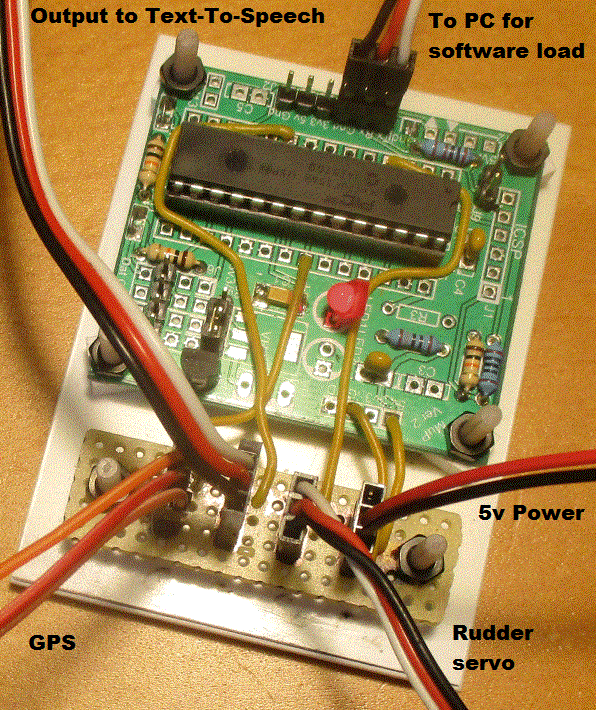 Wednesday 9th August 2017:
I've added this picture to the
MicroMite page. Click on it to see details.
Roy kindly gave me this second working MicroMite, and it can go into an experimental boat, as a straight plug-in swap for our
existing MicroMite. It only took a few minutes to program in Bray Lake waypoints. More signicantly, the "VAR SAVE"
and "RESTORE" statements seem to work, which greatly simplifies the UK to USA logic, which must cope with temporary
power failures. i.e. the Autopilot "remembers" it's current target destination. There are a few problems yet to be solved,
including what appears to be some questions about arrays. I certainly have a minor one or two bugs to fix in the
software: MMAUTOP2.BAS and need to program around any restrictions. It's possible that we may switch from Picaxe
to MicroMite for next year's boat, after a day or two of software work and a few months of testing :-)
Tuesday 15th August 2017: FAILURE OF SERVO ON 24/7 TEST. See 27th July above. The first Etronix ES030 3.0kg Analogue STD Waterproof servo has failed after just 18 days. i.e. ~ 2.5 weeks. The 2nd Etronix E5030 started it's 24/7 test at ~ 1700. The first Carson servo is still running. See 7th July above. That's 5 weeks. We are hoping for at least double that. i.e. MTBF of nearer 2 or 3 months, like the old Acoms AS-17. Good progress also being made with Roy's 2nd MicroMite board and we may sail it in Boat12 on Bray Lake tomorrow.
 Wednesday 16th August 2017:
FAILURE OF CARSON SERVO ON 24/7 TEST. I guess I spoke to soon: solar battery was only 4.77v, but same with charged 5.6v:
The other new Etronix servo was OK, but our first Carson servo only lasted just 16th Augus minus 7th July = just over 5 weeks. A second Carson servo was put on 24/7 test at 0950.
So we are still on the lookout for a reliable Acomms AS-17 replacement.
Details of what happened, and why, in today's Bray Lake Tests are in
Blog6
. Enjoy one of the videos here ! :-)
Wednesday 23rd August 2017:
Time for a bit more "work" on the experimental MicroMite Autopilot, for testing in Eric's Boat 12, starting a new program, MMAP1A.BAS "Alpha",
based on MMAUTOP2.BAS. Bugs are being corrected, but main change is code to define waypoints, to make it easier for extended Team-Joker
to see my mistakes or perhaps offer their own waypoints, such as in their own local lakes. Yes, I can hear some of you saying,
"I wouldn't have done it that way" :-)

 Code now Snoopy's experimental MicroMite Autopilot "Alpha" (MMAP1A.BAS) to define waypoints and routing...
WPName$( 1 ) = "Robin's Corner" : WPlat!(1) = 51.397000 : WPlon!(1) = -0.659833 : WPRad!(1) = 0.002 : WPNextWP%( 1 ) = 3
WPName$( 2 ) = "Robin's Doorstep" : WPlat!(2) = 51.396951 : WPlon!(2) = -0.660053 : WPRad!(2) = 0.002 : WPNextWP%( 2 ) = 1
WPName$( 3 ) = "Back Garden" : WPlat!(3) = 51.396995 : WPlon!(3) = -0.660406 : WPRad!(3) = 0.002 : WPNextWP%( 3 ) = 2
WPName$( 4 ) = "Base" : WPlat!(4) = 51.5001 : WPlon!(4) = -0.6901 : WPRad!(4) = 0.003 : WPNextWP%( 4 ) = 5 'at Base go to Alpha
WPName$( 5 ) = "Alpha" : WPlat!(5) = 51.4995 : WPlon!(5) = -0.6910 : WPRad!(5) = 0.003 : WPNextWP%( 5 ) = 6 'at Alpha go to Bravo
WPName$( 6 ) = "Bravo" : WPlat!(6) = 51.4995 : WPlon!(6) = -0.6930 : WPRad!(6) = 0.003 : WPNextWP%( 6 ) = 7 'at Bravo go to Charlie
WPName$( 7 ) = "Charlie" : WPlat!(7) = 51.4990 : WPlon!(7) = -0.6920 : WPRad!(7) = 0.003 : WPNextWP%( 7 ) = 8 'at Charlie go to Delta
WPName$( 8 ) = "Delta" : WPlat!(8) = 51.4990 : WPlon!(8) = -0.6900 : WPRad!(8) = 0.003 : WPNextWP%( 8 ) = 4 'at Delta go back to Base
![]()
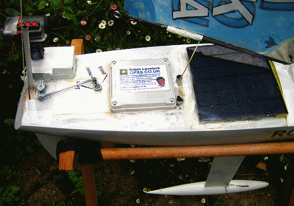
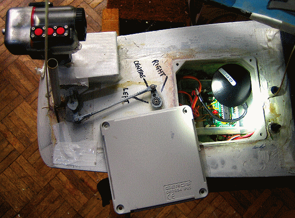
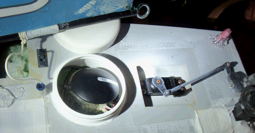 But some work had to be done on Boat12 hardware. Click on the pictures to enlarge. That circular plastic cover was replaced by a GEROS IP65 box, 10x10x6cm deep, from Maplins.
However, only the top was used, so the 6cm was reduced to nearer 1cm, and a matching hole was cut into the deck. It was then fixed in place
with Isopon P40. The wiring was tidied up, including replacing the wires from the solar panel - the negative (0v) lead was suffering from
"black wire syndrome". The solar panel was then glued back onto the deck with white silicon sealant. The brass tube FM Transmitter mount was connected to 0v. A 5v monitor and charging point was made near the box lid.
Software version "Alpha" was loaded into Roy's MicroMite Board#2, which easily slips into the box, inside a visiting card box. Yes, that
is my visiting card, laminated, glued onto the box lid, say in red, "Retired years ago ! Too busy for paid work ! :-)"
![]()
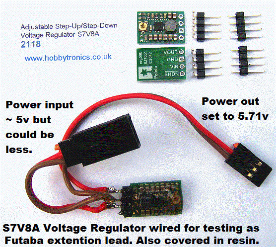
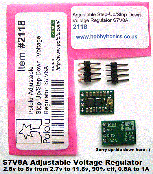 Thursday 24th August 2017:
The six S7V8A Adjustable Voltage Regulators, ordered yesterday, arrived today, and are in my queue of experimental "work".
Click on the picture to read details. Roy had suggested the S7V8A and I was immediately interested in them to be put through thorough tests.
e.g. the actual efficiency, if used to provide a constant 5.7v* from our NiMHd Solar supply. If 24/7 testing after adjustment then covering in resin shows
them to be OK, then we might risk at least one side of our duplicated supply. Maximum drain to Snoopy's electronics, including Autopilot,
is no more than ~50mA, so the claimed 500mA to 1A should mean there are no overheating problems. * Why 5.7v ? So that diodes, dropping
typically 0.7v, can be used to bring together Snoopy's duplicated power, to the 5v used by the Autopilot, including GPS, Computer, and rudder servo.
Tests so far on the S7V8A look good. Futaba male and Female leads were soldered onto the 3 pins ( the shutoff pin will not be used ). This is inserted into the 5v battery supply. It was easily adjusted to 5.71v output with a low battery of 5.24v. The whole card was then covered in Fastglass resin. When connected to 28X2 autopilot the ~60mA only increased by a small ammount: maybe +3mA, but difficult to see because the GPS fluctuates. It had no problem driving the autopilot with servo and TTS unit. It was then inserted into the running 24/7 servo test rig, which has a Picaxe 08M2 and THREE servos. It was left running overnight.
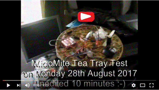
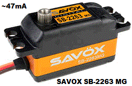 Other "work" today included adding the "Cross Track Error Correction" logic into the MicroMite software version "Alpha". It already seems to work in
the Picaxe 28X2 software within Boat11 for the 2017 Atlantic Attempt. More Tea-Tray testing is needed, but it looks as if Eric's Boat 12 will have another sail soon :-)
Saturday 26th August 2017:
Tea-Tray Testing revealed error in "Back Garden" Longitude above: now -0.660406. More testing is needed, but Dick and I will probably give it a try :-)
Sunday 27th August 2017:
Peter's SAVOX Brushless servo was tested for current drawn, and - as he said - it was MUCH more than all the others that draw about 6mA.
When static this drew 47.1mA from 5.49v. It therefore does not qualify for use in Snoopy's robot boats, as an alternative to the obsolete
Acoms AS-17. For those who might consider it, the full name is "SAVOX Digital SB-2263 MG DiGiT 4096 Brushless Servo".
At 0900 I put Stuart's servo on 24/7 test, joining the others, such as the Carson. The "Spektrum DS821 Digital made in Malaysia" draws 9.2mA.
Monday 28th August 2017:
The 10 minute MicroMite Tea Tray Video shows the latest software change to "Alpha" ( MMAP1A.BAS ) being tested: spoken position relative
to the nearest waypoint, so we can hear if the GPS position is "wandering around". After Board#1 testing on the PC, then the tea tray,
the software is put into Board#2, in Boat 12, for Bray Lake Test. "Change a Little, but Test a Lot" as someone told me ;-)
Thursday 31st August 2017:
( Copied or moved from
Blog6
because mosty "experimental" )
In brief: Peter, Roy, Dick, and Robin put together kit for Boat11 and Boat12, before pub grub then several hours at Bray Lake,
in extremely light wind conditions: ending in dead calm. Boat12 with the MicroMite Autopilot did two circuits quicker than Boat11,
which needed help for the last few yards, by Paul, the friendly paddleboarder. The GPS logger plot for Boat12 is in
31081712.nme
* . That for Boat11 is in
31081711.nme
.
* to be split into two plots, when Robin knows launch times.
Version Quebec does seem to keep the boat on track, between waypoints, but we obviously need to test in stronger winds.
Click on pictures to enlarge. We may have the video here tomorrow.
Friday 1st September 2017:
The edited 29 minute video is on the right. For those interested, there is also the 1.7 hours from the Mobius on Boat 12 :-)
![]() Saturday 2nd September 2017:
Notepad was used to split
31081712.nme
into the two Boat12 MicroMite trips
310817a.nme
and
310817b.nme
used for the seperate plots below.
Click on them to see details.
Over-shooting of waypoints can be fixed with a software change.
MMAP1A.BAS "Alpha" now has 15m instead of 3m thresholds, for waypoints A,B,C,D.
"Base" is 3 metres, to reduce risk of Snoopy setting off to "Alpha" again before we grab him ! :-)
Saturday 2nd September 2017:
Notepad was used to split
31081712.nme
into the two Boat12 MicroMite trips
310817a.nme
and
310817b.nme
used for the seperate plots below.
Click on them to see details.
Over-shooting of waypoints can be fixed with a software change.
MMAP1A.BAS "Alpha" now has 15m instead of 3m thresholds, for waypoints A,B,C,D.
"Base" is 3 metres, to reduce risk of Snoopy setting off to "Alpha" again before we grab him ! :-)
![]()
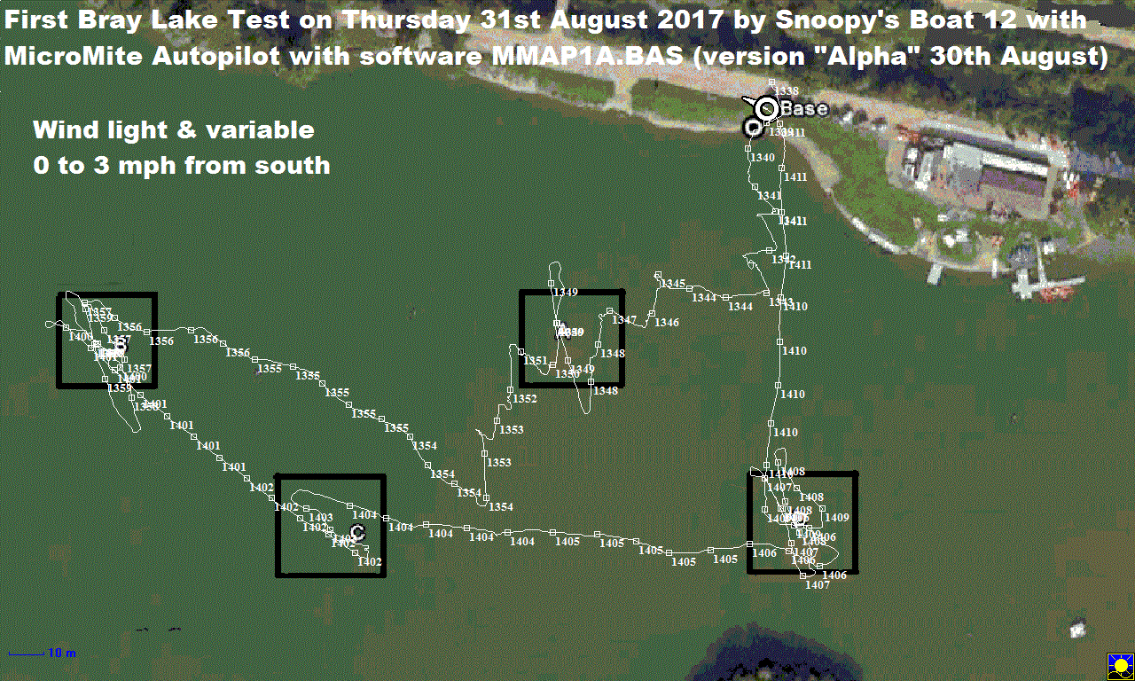
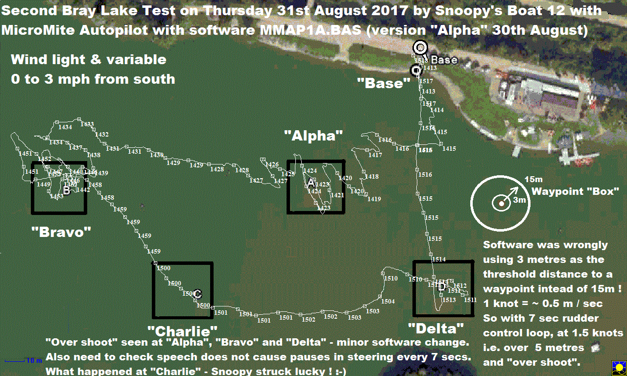
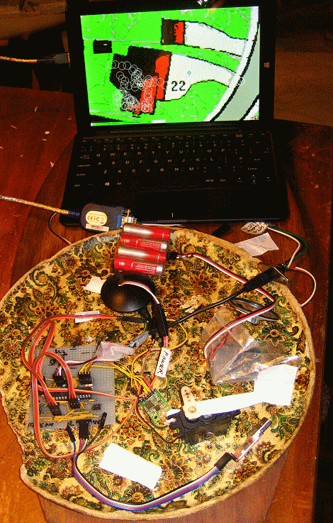
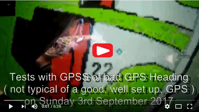
![]()
 Monday 4th September 2017:
Stuart's Spektrum DS821 servo failed, after 8 days 24/7 test. See 27th September above. It was hot at the bottom.
See
Blog6
for details of "bad GPS heading" problem on BR355-S4 GPS. The MicroMite Tea Tray Test video is now above.
Wednesday 6th September 2017:
SERVO FAILURE: The second Etronix ES030 Waterproof Servo failed after just 22 days 24/7 test. The first lasted just 18 days.
See 27th July and 15th August above. This product is therefore not suitable for Snoopy's robot boats, having a MTBF of ~ 3 weeks.
Our BR355 "bad GPS Heading" problem
continues. See
Blog6
.
Friday 8th September 2017:
SERVO FAILURE: the second "CarsonREFLEX Racing Servo CS3" failed, having been put on 24/7 test on 16th August (see above).
That's just 23 days (3 weeks+). The first lasted over 5 weeks, so it seems the MTBF (Mean Time Between Failure) is only about 4 weeks.
So we are still looking for a servo to compete with the obsolete Acoms AS-17 on reliability.
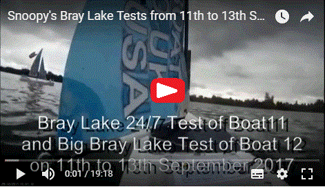
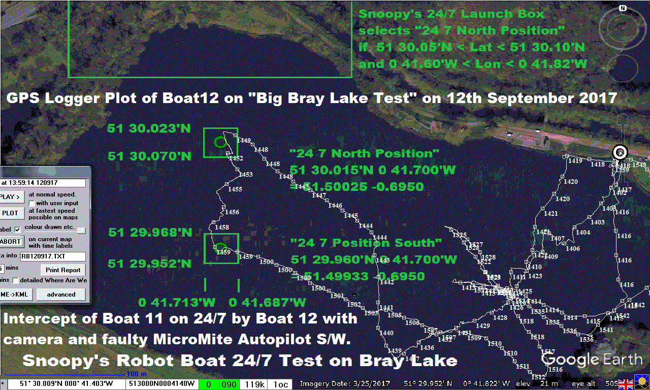
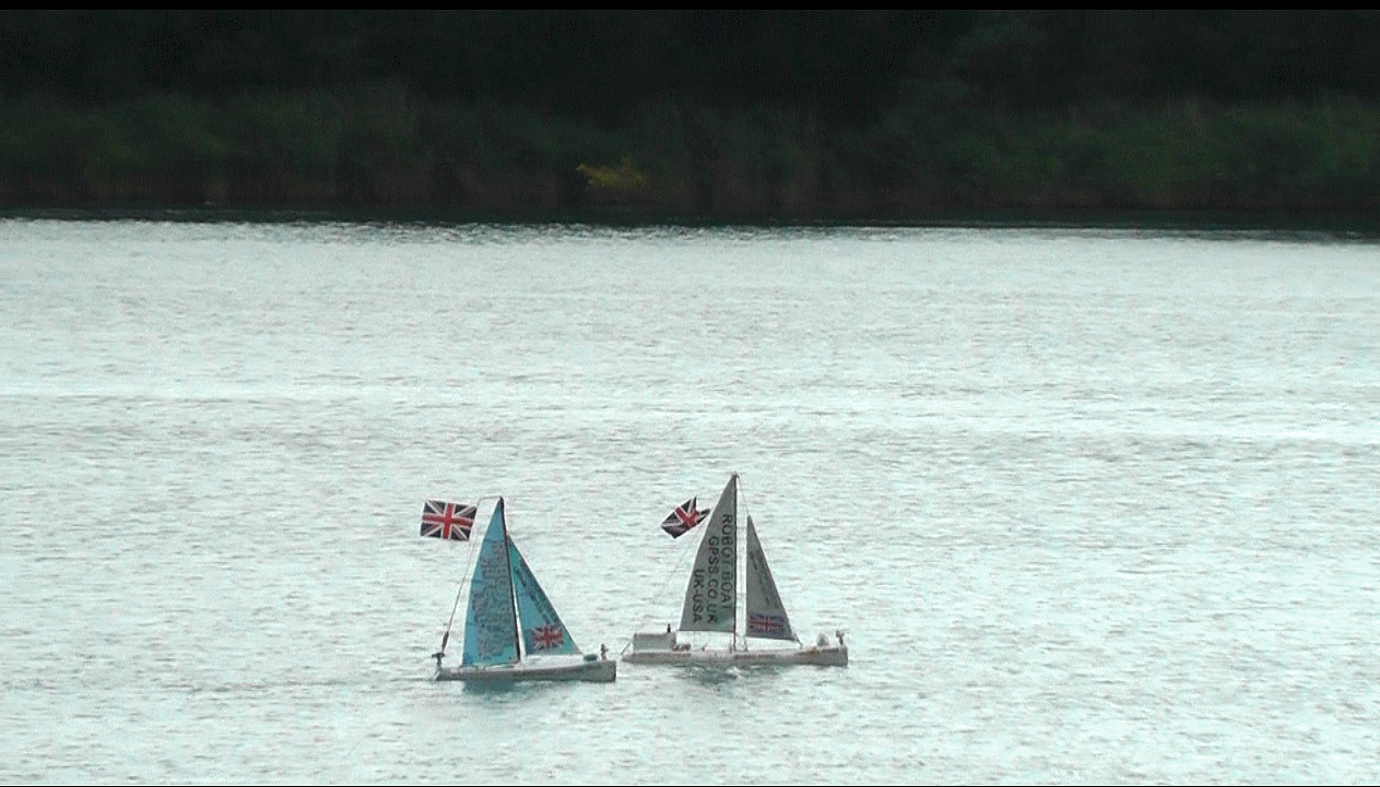 Thursday 14th September 2017:
Click on these pictures and video from
Blog6
where Boat 11 is being 24/7 tested, prior to it's 2017 Atlantic Attempt.
Boat 12 is experimental, and carries the new MicroMite Autopilot.
The software still has bugs, but it managed a "Big Bray Lake Test",
Base->A->B->247North->247South->C->D->Base, carrying the Mobius video camera.
The terrible steering over most of the route was a silly bug, now fixed, in
cross-track-correction.
![]()
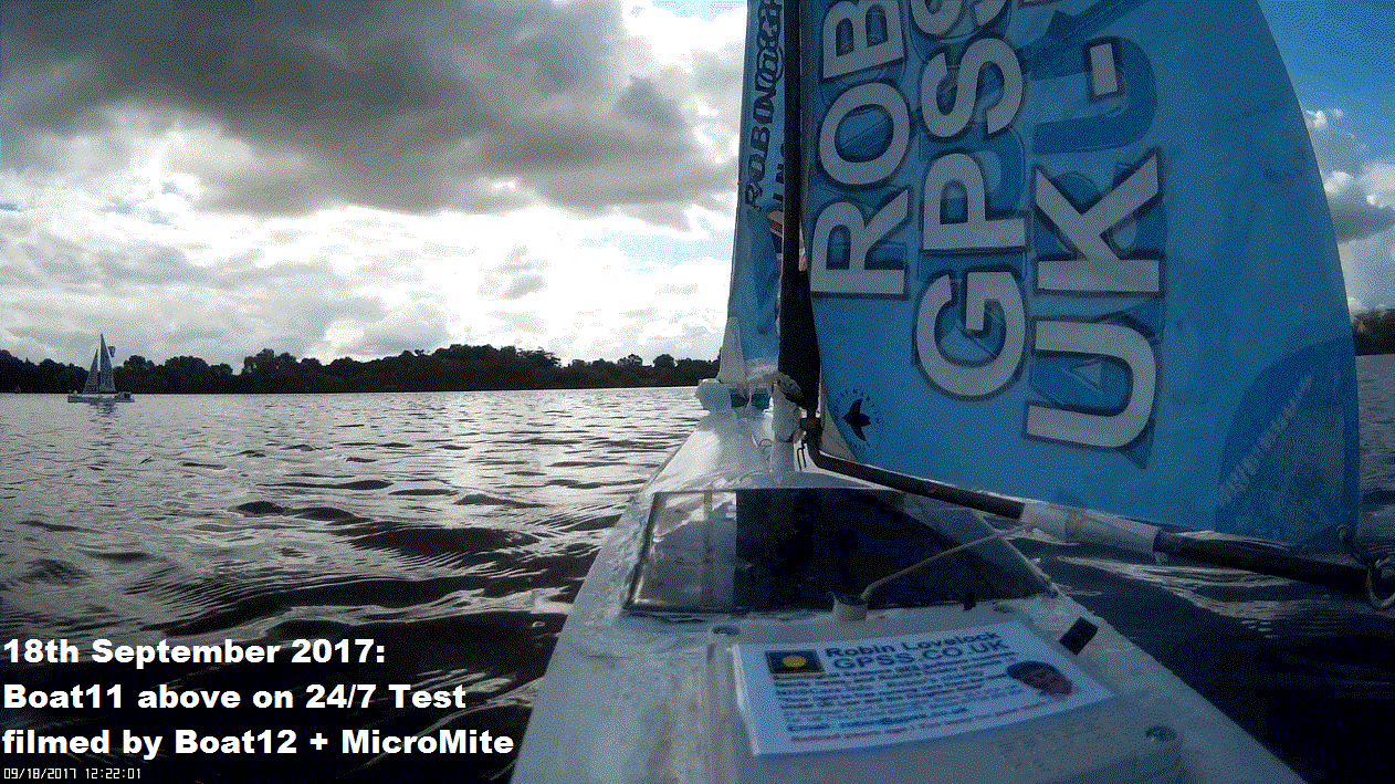
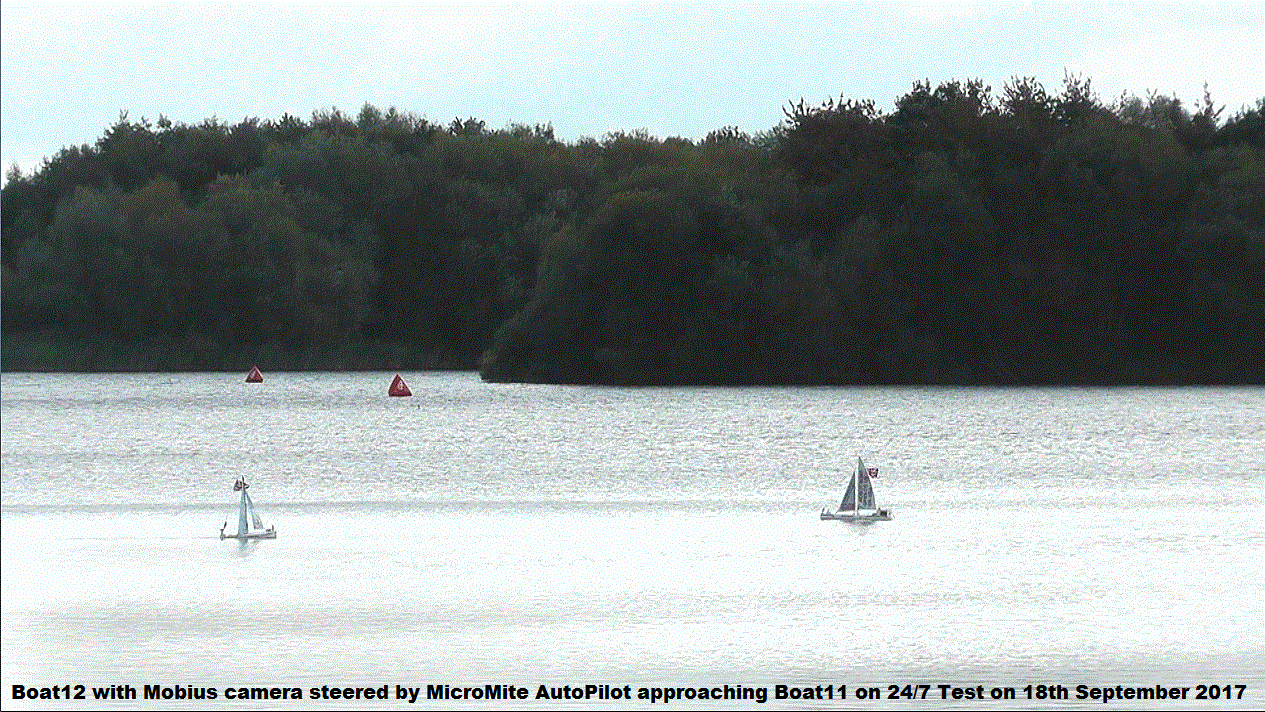
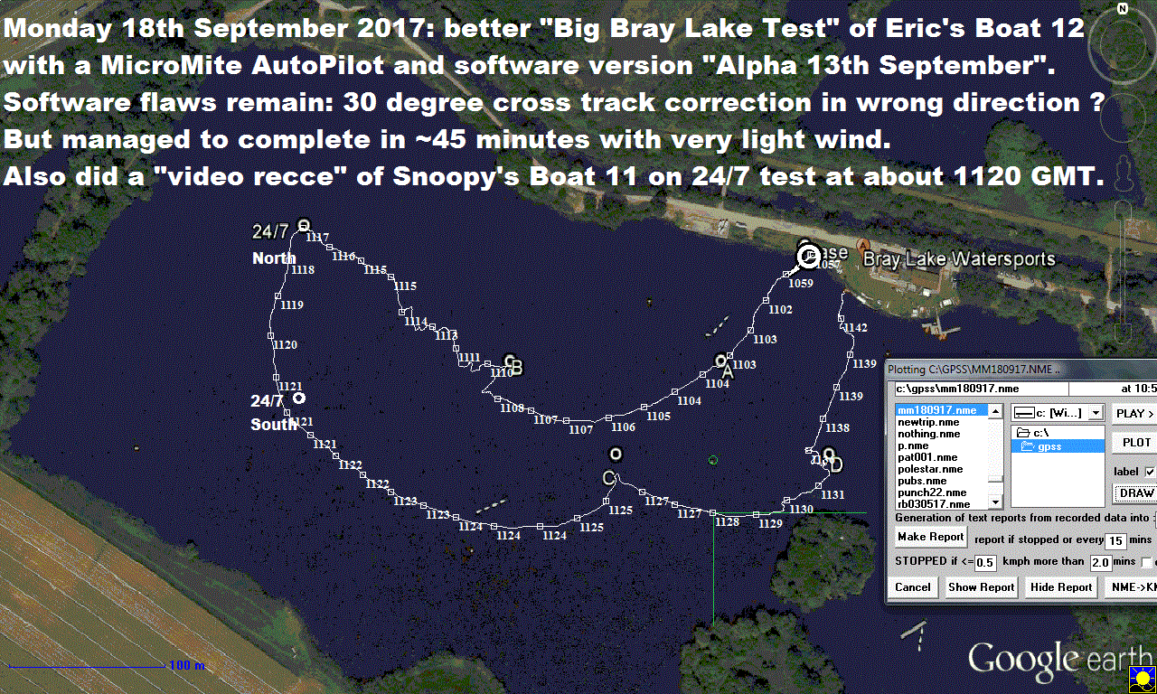 Monday 18th September 2017:
Boat 12 did a "Bigger Bray Lake Test" in about 45 minutes, despite light wind and what appears to be a remaining bug or flaw
in the software. e.g. the 30 degree cross-track correction being applied in wrong direction ?
The GPS Logger data from Boat 12 is in
mm180917.nme
.
Check out the video. Not a bad hour at Bray Lake :-)
![]()
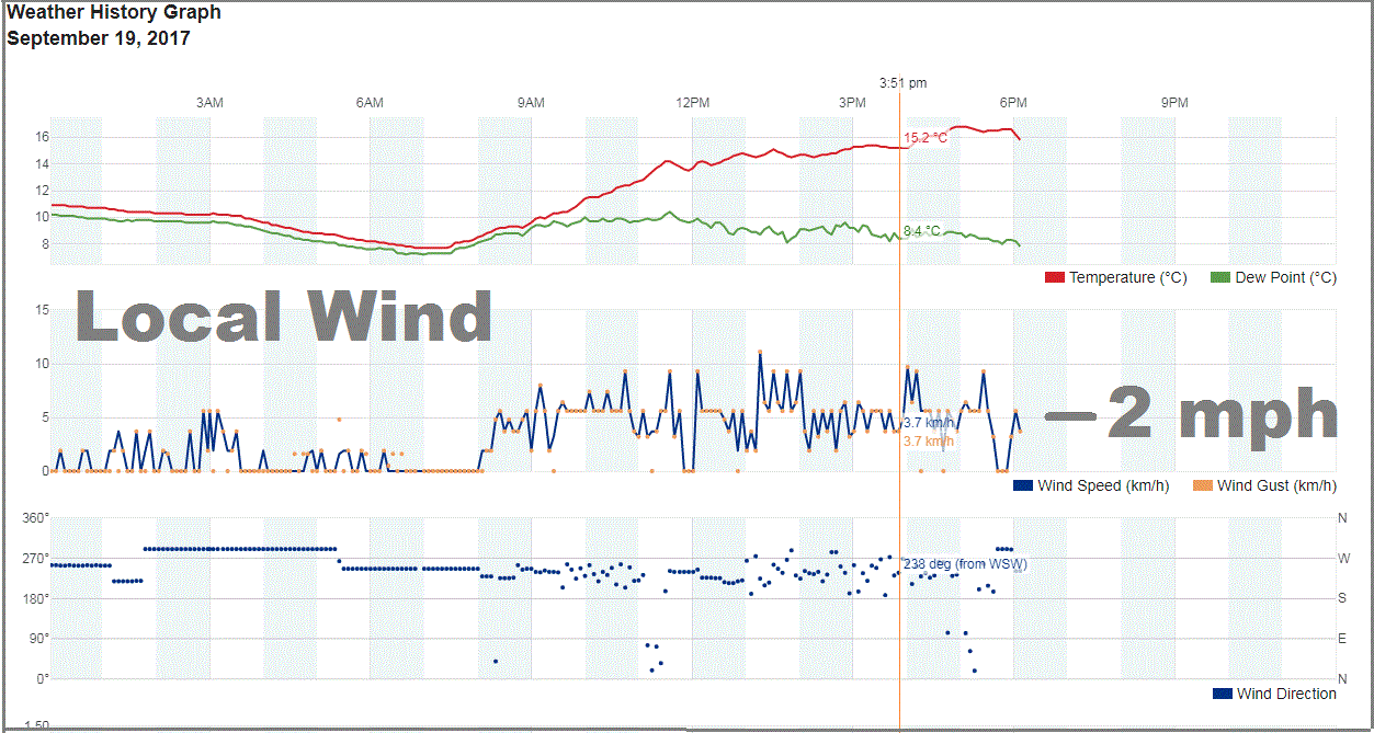
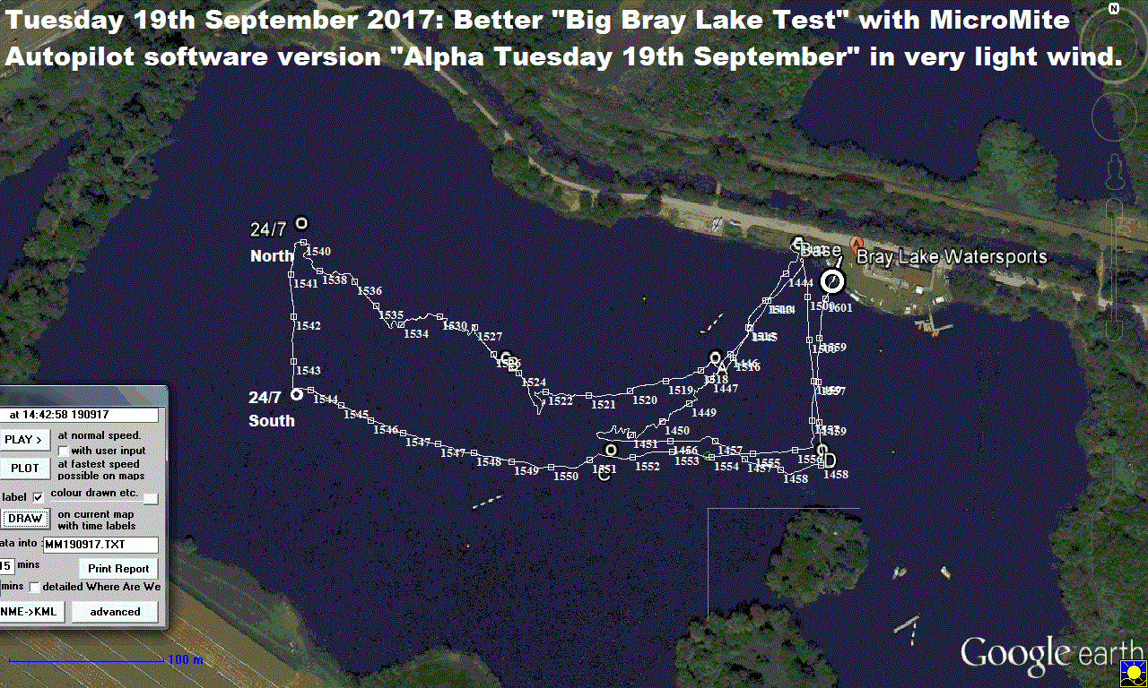 Tuesday 19th September 2017:
Boat 12 did a straighter "Bigger Bray Lake Test" after today's change to the experimental MicroMite Autopilot software "Alpha".
The GPS Logger data from Boat 12 is in
mm190917.nme
.
The video Mobius deck camera has yet to be looked at, but it seems that the wind was even lower, at an average of 2mph or lower.
This may explain that "false start" where Boat12 drifted into Waypoint Charlie, and cut the mission short.
I hope to add more tomorrow: it's a busy day today, including EASAMS Pub reunion and Italian lessons tonight.
Terry and I chatted to two Radio Hams: see WSPR on the
Radio
page. The extra MicroMite Autopilot boards arrived from Phil: more in due course.
Wednesday 20th September 2017:
The video shows things like sailing in very light wind, the intercept, and minor bugs remaining. e.g. Course between waypoints "-90" not "270".
![]()
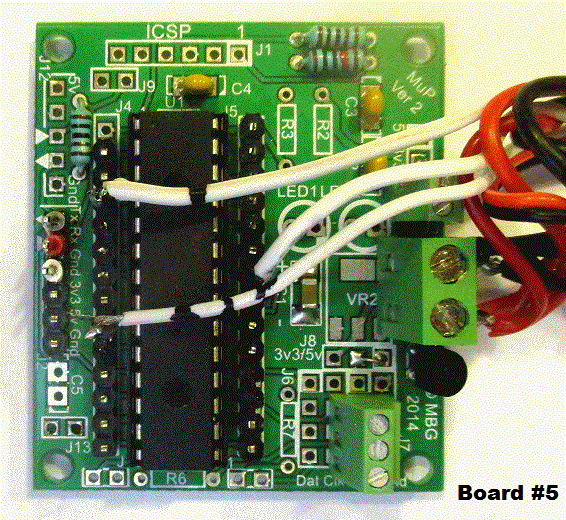
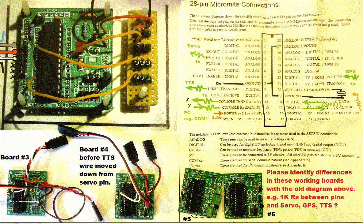
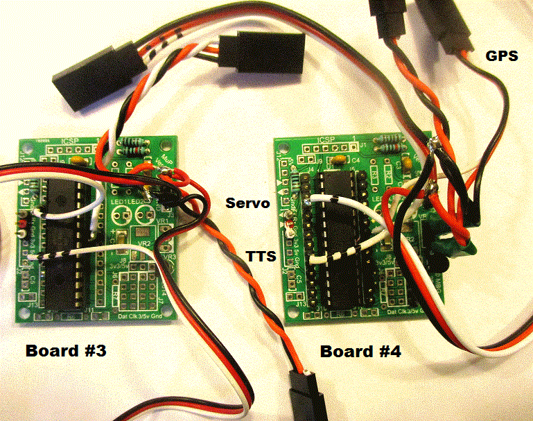
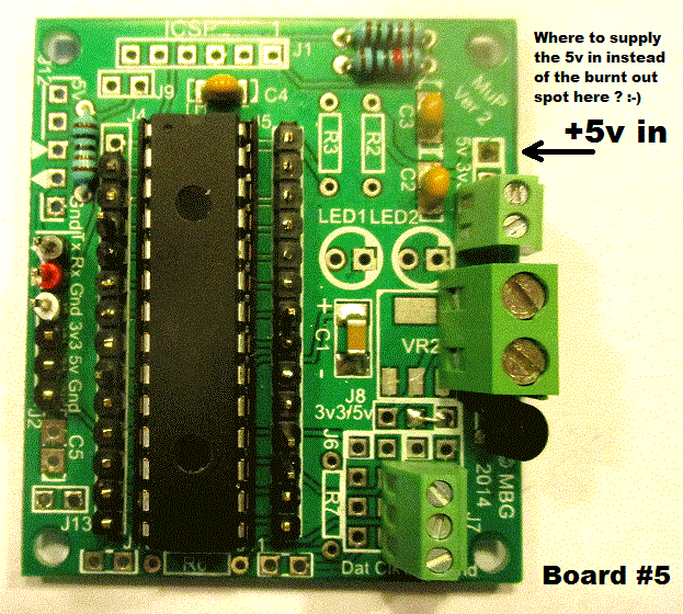 Thursday 21st September 2017:
Good progress was made exploiting the help given by Phil in supply of MicroMite AutoPilot boards, including fixing Robin's mistakes
- such as burning out that 5v pin track on Board#5 !
Click on these photos used in emails. All four boards have now been loaded with the latest MMAP1A.BAS software, and work with TTS, Servo and GPS.
We may be popping some into other boats soon :-)
![]()
Friday 22nd September 2017:
Today's bright idea worked well: Minor software change to create version "Beta" of the MicroMite Autopilot software in MMAP1B.BAS to include
two waypoints at Horsehoe Lake. Peter, Dick and Robin met there at 1215, watched Snoopy complete two missions well, before conducting a
technical meeting over lunch at The White Lion pub. The GPS Logger data is in
mm220917.nme
. Click on pictures to enlarge. The video comes later - best wishes to Alex and Charlie ;-)
Saturday 23rd September 2017:
The 20 minute video is now below. Robin changed the software so "Target Beaujolais Bully" is "Target Horseshoe Lake Buoy": see the
follow-up
2 minute video
.
The main video starts with Dick tightening the jib, so the mainsail boom did not hit the deck.
This is now bodged properly: held the boom up, while brass tube, soldered wire, and Isopon P40 was
used to raise the mast; 3-IN-ONE oil, so the boom swings more freely; Duck tape changed, holding the jib sail to it's boom. That'll do :-)
![]()
Monday 25th September 2017:
Click on pictures below for details of Snoopy's
Windmill Boat
, being converted to one for rescue. It's first mission may be to collect Snoopy's Boat 11 on 24/7 for the past 9 days,
and save us asking the Clubhouse for a rescue. It may also come in handy if we try missions in less friendly places.
The radio receiver can come out of the
Sailing Saucer
and I now have a speed controller, for slow and reverse: from Mantua Models - the Mtroniks Viper Marine 10. The old Windmill boat only did full speed ahead.
Grab height looks similar on Boats 12 and 11. It did not take long to put the radio control bits together. It's now ready to test on water and grab Boat 11. What could go wrong ? :-)
![]()
![]()
 Wednesday 27th September 2017:
Here on the far right is a video made this morning, to help Jesse at Globalsat US diagnose what
I've done wrong in the setup procedure, to remove, not only Static Navigation, but also "Smoothed Heading",
on one of the Globalsat BR355-S4 GPS obtained via DigiGomart. All the others in that batch did not
have this problem, reported on 3rd September in
Blog6
- work on this year's Trans-Atlantic Boat. I've repeated that entry below.
Solving this problem may now be regarded as "Experimental", since all our other GPS are OK.
Most of the 12 minutes are nitty-gritty on today's tests, and applying the Patch,
then switching off Static Navigation with SiRFDEMO. This should be of use to
others in Team-Joker using the BR355-S4. I also include a few minutes at the start
that may be of interest to Globalsat in Taiwan, depending on their business situation.
In recent years, I've had more contact with Shenzhen than Taipei.
Now that entry from from Blog6:
![]()

 from Sunday 3rd September 2017 in
Blog6
This may belong in
BlogX
, with other "experimental" work, but it has enormous significance for our GPS-Only autopilots, that use the GPS Heading.
In brief: yesterday, using my old GPS Software, GPSS, running on a Linx 10, to monitor the same GPS data being fed into
a MicroMite Autopilot, I saw a massive delay in the direction of movement. All GPS, when properly set up, should update
both GPS Position and velocity accurately, every second. Velocity is speed, and the "GPS Heading" or "Course Over Ground",
critical to our GPS-Only or Hybrid Autopilots. It is probable that this problem can be fixed by changing the Globalsat BR355-S4
settings. If not, the GPS will need to be changed. This is the first time Robin has seen this problem in decades
of working with GPS. Priority tasks are to see if our Picaxe 28X2 Autopilot in Boat 11, being prepared for the 2017
Atlantic Attempt, has this problem*. Also, our spare GPS-Only autopilots. It is also of critical importance to longer term
experimental work, such as the new MicroMite based Autopilot. Robin must have wasted several hours looking for
software bugs, when the poor steering was down to the poor data coming from the GPS ! * Good News update at 1430: a tea tray test
of Boat11's Autopilot showed rapid rudder turning, in the correct direction, within the 7 second control cycle.
This is the same type of Globalsat BR355-S4 GPS, with "G-Star IV" written on it's black plastic case.
More Good News at 1500: Boat12's MicroMite Autopilot, with a BR355-S4, loaded with same latest version "Alpha" of software,
worked OK, with rapid steering changes in response to change of movement direction. So perhaps it's just this one BR355
that needs to be fixed.
Footnote on Wednesday 6th September 2017:
Thanks to Jesse at Globalsat in USA, we are trying a firmware patch that I have saved in
rbpatch2.zip
. Running the patchS4_S-0PC-12-1307121.exe applied the patch, but this is still
our old Version2:F-GPS-4R-1201127. This seems to be the same EXE as in our old patch.
This firmware should have static navigation & smooth heading filtering disabled.
We still seem to have smooth heading filtering enabled.
Wednesday 27th September 2017 again:
That video of today should be of help to Jesse and others, including Globalsat in Taiwan and Robin's Team-Joker friends ;-)
Thursday 28th September 2017:
BR355-S4 files in
f-gps-~1.zip
applied, but no fix yet. Mobius camera time set: now BST+9sec; was +75sec.
![]() Sunday 1st October 2017:
Click on pictures below to see detail.
Blog6
reports that Snoopy's Boat11 for this year's Atlantic Attempt is now ready, and waiting.
We can experiment and "think laterally" on things like boats for next year.
Robin had a week unhampered by women, so Team-Joker were able to visit Screwfix, near RAE Fanborough,
then meet in a pub for discussion. e.g. Roger's idea of Dam Buster's ranging with two torches.
Snoopy's Windmill boat is being improved for use a "rescue" boat.
The map shows Bray Lake and Eton Boating Lake, also used for Snoopy tests.
These days Robin prefers paper maps, until June's smart 'phone is as good as his ancient
Pocket PC
- with Snoopy's first AutoPilot :-)
Sunday 1st October 2017:
Click on pictures below to see detail.
Blog6
reports that Snoopy's Boat11 for this year's Atlantic Attempt is now ready, and waiting.
We can experiment and "think laterally" on things like boats for next year.
Robin had a week unhampered by women, so Team-Joker were able to visit Screwfix, near RAE Fanborough,
then meet in a pub for discussion. e.g. Roger's idea of Dam Buster's ranging with two torches.
Snoopy's Windmill boat is being improved for use a "rescue" boat.
The map shows Bray Lake and Eton Boating Lake, also used for Snoopy tests.
These days Robin prefers paper maps, until June's smart 'phone is as good as his ancient
Pocket PC
- with Snoopy's first AutoPilot :-)
Monday 23rd October 2017: After problems with wind noise on recent videos in Blog6 , Peter and Dick nagged Robin into buying this microphone wind muffler on his hand held camera. June paid for it on Amazon, so quickly decided to give Robin a bit of fluffy material, now stuck with bostic onto his camcorder internal stereo mike, and FM Bug transmitter. Robin has shelved his work on the spare GPS Logger, after several hours work, with soldering iron and 'scope, without reward. We still only get a blank file written on the SD card, after trying things like extra 1.2K across the 10k resistors (were those 10k values on 3rd August correct?), and then swapping the Ardulog for a new one.
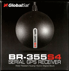
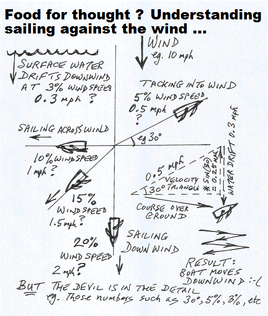 Thursday 2nd November 2017:
Most of recent Snoopy activity was reported on
Blog6
, but this "Food for thought" sketch from yesterday can be repeated here.
Today the two BR355-S4 from Globalsat in USA were tested, and found to be perfect,
without need for any setup. The startup NMEA data with version details is below.
Click on pictures to expand.
$PSRFTXT,Version: GSD4e_4.1.2-P1_RPATCH.03-GNC03*0C
$PSRFTXT,Version2: F-GPS-4R-1312231*69
$PSRFTXT,SBAS: Enabled*3F
$PSRFTXT,TOW: 383494*14
$PSRFTXT,WK: 1973*69
$PSRFTXT,POS: 3987435.1 -45931.4 4961343.5*15
$PSRFTXT,CLK: 95709*2F
$PSRFTXT,CHNL: 12*73
$PSRFTXT,Baud rate: 4800*65
etc, etc, etc
$GPRMC,103120.601,A,5123.8262,N,00039.6109,W,1.22,184.46,021117,,,A*7F
Boat 12 power wiring seemed unreliable, so was replaced with new Futaba connectors. This is now our "reference boat", for comparisons.
The spare GPS Logger is now fixed: the Ardulog was replaced. The inverter board was put back to 10k resistors from 1k. Now on Boat 12.
![]()
Monday 13th November 2017:
following is in
Blog6
page:
Boat 11 now has a skeg, to increase Lee Helm, and now seemed a good time to compare the two boats, with this in mind.
The video below shows a new idea for combining the GPS Logger data and Mobius video, as a means of analysing
results from a Bray Lake Test. Another idea is the polar plot from the GPS Logger data, showing how fast the
boat travels in different directions relative to the wind.
More detail will appear on the BlogX page.
Here is that detail ...
The Polar plot is an idea from Peter, who wrote the software. Reading of the GPS Speed and Heading is not difficult,
from the data in the GPS Logger file: in this case
rx051117.nme
.
Note this is GPS data for Boat 12, NOT Boat 11 seen in the GPSS/Mobius video below.
$GPRMC,114827.000,A,5129.9443,N,00041.5303,W,1.88,103.64,051117,,,A*72
e.g. above GPS Logger data is at 1148+27 secs, 1.88 knots, with boat moving in a direction of 103.64 clockwise from North.
This idea may be exploited with sailing missions, such as big circles, to evaluate a particular boat and/or sail settings.
GPS Loggers may have a compass added, so boat heading is also logged: not just the direction that the boat is moving.
Tuesday 14th November 2017:
Trying to match the timing of the GPS data replay, and the Mobius video, is made more difficult by that important $GPRMC GPS time
being too small to see in the "GPS Engineering Information" window. This work is not helped by problems with both alternative
video editors: Nero Video and Videopad. We still need to confirm two reference times, near start and end, on both videos,
to get them to match. This may need using Videopad to speed up or slow down the GPSS replay video. Another video, with $GPRMC GPS time
large enough, would help. Robin's suggested start and end times, shown below, are: Start 1218+30 seconds - as Boat 11 makes a sharp turn left,
near Bravo; End at 1229+40 secs - as Boat 11 comes alongside the jetty. An extract of the GPS Logger data, covering this period, is in
gpsmob1.nme
.
Any assistance would be gratefully received :-)
Click on pictures to expand or play.
![]()
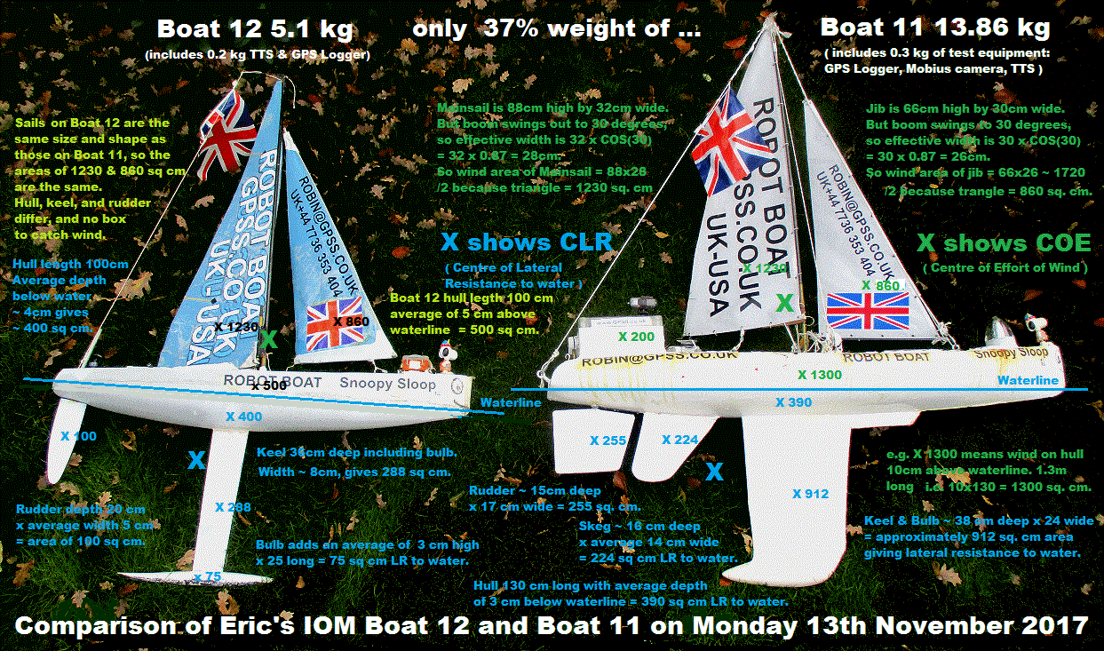
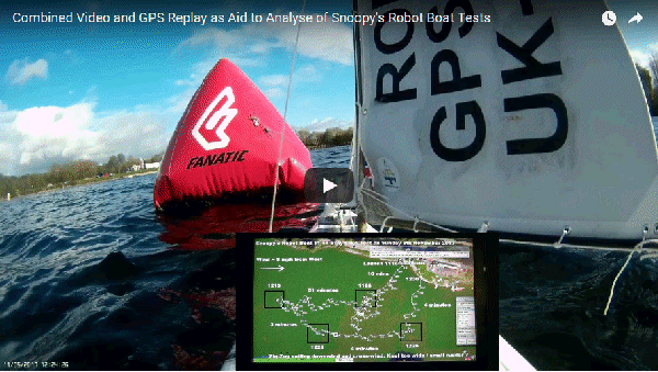
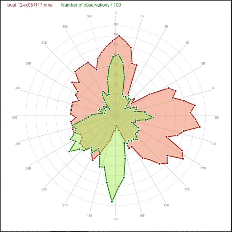
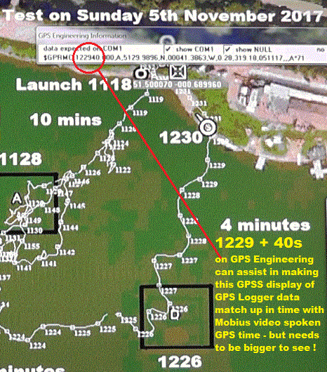
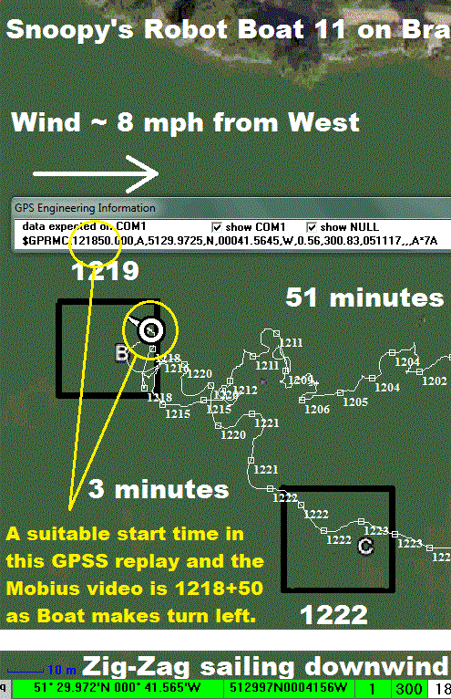
![]()
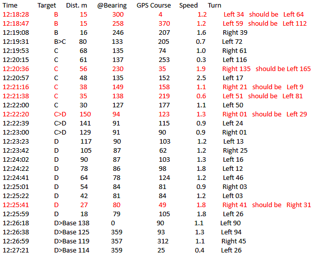 Wednesday 15th November 2017:
Below is the combined GPSS/Mobius video, with timing OK. Videopad was used to speed up the GPSS
video clip by 10%, and the Mobius video shifted to the right by 12 seconds. The screen layout seems more suitable,
with the Mobius window shifted to left when GPS track moves near Delta then Base.
Some titles and a clip or two from the 5th November video in
Blog6
, also below.
Thursday 16th November 2017:
Another "bright idea": see rudder position, including trim, on Mobius Video. e.g. a plug in external servo with a dial ?
Friday 17th November 2017:
It did not take long to add the extra Futaba lead, out of the box, and make the "Rudder Dial". More importantly: the
Mobius cameras have more suitable settings than what we've used for years. e.g. Video resolution reduced and pressing
the ON/OFF switch starts the video rolling.
Peter, Dick, and Roger, of Team-Joker, have given Robin valuable tips on making these combined GPSS/Mobius videos.
e.g. The video editor Videopad is used to speed up the GPSS video by 10% using the factor 110.00%.
This is being refined to nearer 110.7%. Instead of making the GPSS video by pointing a camera at a PC screen,
Debut is used instead, running in the same PC as GPSS. Our test equipment may be improved further.
e.g. our GPS logger having the option to log GPS data ( for GPSS replay ), from the Autopilot GPS.
i.e. to confirm that it is not being upset by nearby electronic equipment like the SPOT Trace.
Videos below are: the full 5th November video from Blog6; the final GPSS/Mobius Combined video;
Snoopy's Rudder Dial.
Saturday 18th November 2017:
Minor edits were made above for clarity.
Thanks to Dick for his transcript on the right, that any of us can check, looking for bugs.
Click on pictures to play or expand.
![]()
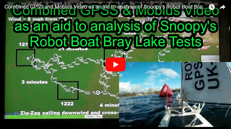
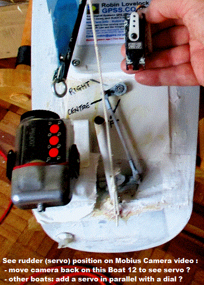
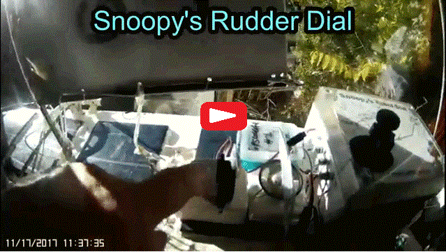
![]()
Sunday 19th November 2017:
Click on pictures to enlarge or play: Kit now on Boat 11. Anyone want to swap Ardulogs I may have blown up for a less clunky clock ? :-)
![]()
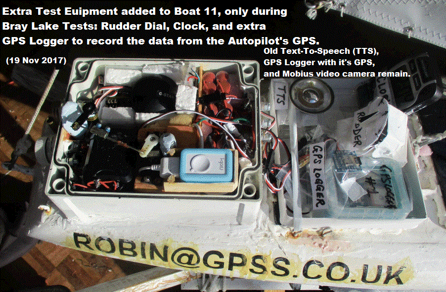
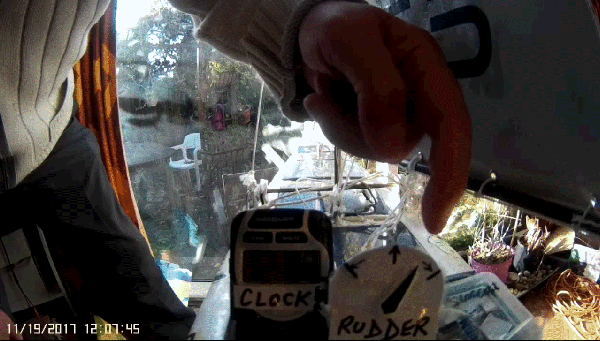
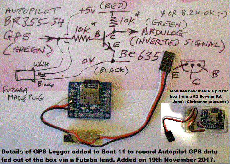
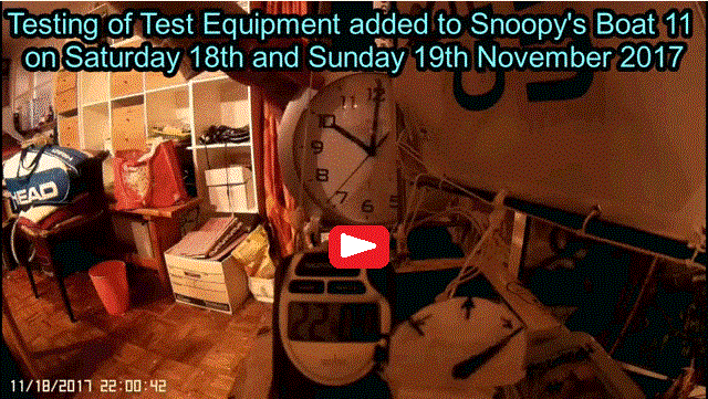
![]()
Tuesday 21st November 2017:
The video below, originaly intended for here, is now also on Robin's
Home
page.
GPSS can also easily be applied to things like replay of a race between two or more boats
( multi vehicle tracking on the
AVL/Chase
page ). Also the display of both boat heading and GPS heading - often not the same
( by use of the DF line on the
Direction Finding
page. Not essential to look at this documentation: just use Notepad to look at files
from the free GPSS.ZIP on the
Download
page, such as
GPSS.NME
,
DFDEMO.NME
,
GPSS.MVD
,
and/or
DEMO.MVD
. Or just ask Robin for a simple example, such as:
$GPRMC,114827.000,A,5129.9443,N,00041.5303,W,1.88,103.64,051117,,,A*72 (GPS Time, position, speed, direction, from a GPS Logger )
%090/8 (draw a line eastward from the last GPS Position, from a Compass )
02>GPSS ( 2nd Boat when multi vehicle tracking - preceeds the $GPRMC for that boat )
Robin is working on what is a trivial little program: to merge two GPS Logger NME files, from Boat 11 and 12 having a race,
into one NME for GPSS Replay and mixing with synchronised Mobius video. i.e. User enters the two input file names, the start
and end times, and the output file name for GPSS Replay.
Boat 12 now has it's extra box at front, to house experimental kit, like Peter's GPS/Compass Logger.
Boat 12 now 5.14kg.
Click on pictures to enlarge or play.
![]()
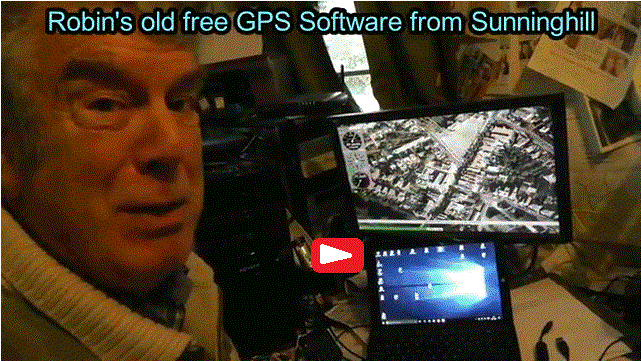
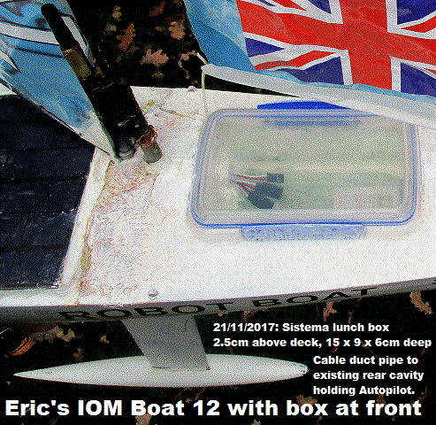
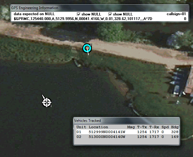
![]()
![]()
THIS COPIED FROM
Blog6
BECAUSE ALSO IN THE "EXPERIMENTAL" CATEGORY ...
Thursday 23rd November 2017:
The video from yesterday is now above. Today, in even stronger wind, Peter, Dick, and Robin, took both boats for
Bray Lake Test. Boat 11 eventually completed the circuit, and Boat 12 did it faster.
However, on Boat 12's second attempt, it took on lots of water. It was rescued by Dick in his dingy,
in shorts - despite the cold :-)
Friday 24th November 2017:
Boat 11 GPS logger data is in
rb231117.nme
and that for Boat 12 in
rx231117.nme
.
Click on the GPS Logger plots below to enlarge.
Saturday 25th November 2017:
15 minute "Quick" Bray Lake Test below shows good upwind to Delta, but zig-zag sailing back to Base.
Next video below is to assist understanding of the Zig-Zag path: Combined GPSS replay and Mobius video, from "Bravo" at 1542,
cross-wind through "Charlie" (1544) to "Delta" (1551), then downwind back to "Base".
This extract of the GPS Logger data is in
re231117.nme
.
The full video record of the day shows both Boat 11 and Boat 12 - getting flooded and rescued !
Videos reveal that Boat 11 selected "Delta", near the island, instead of "Alpha",
due to a fluke in startup GPS location.
Monday 27th November 2017:
See first video.
Click on pictures to play or enlarge.
![]()
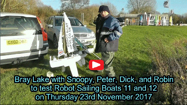
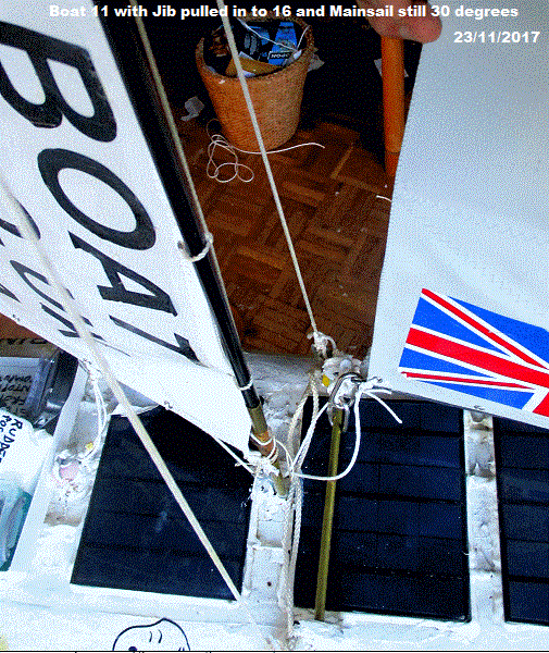
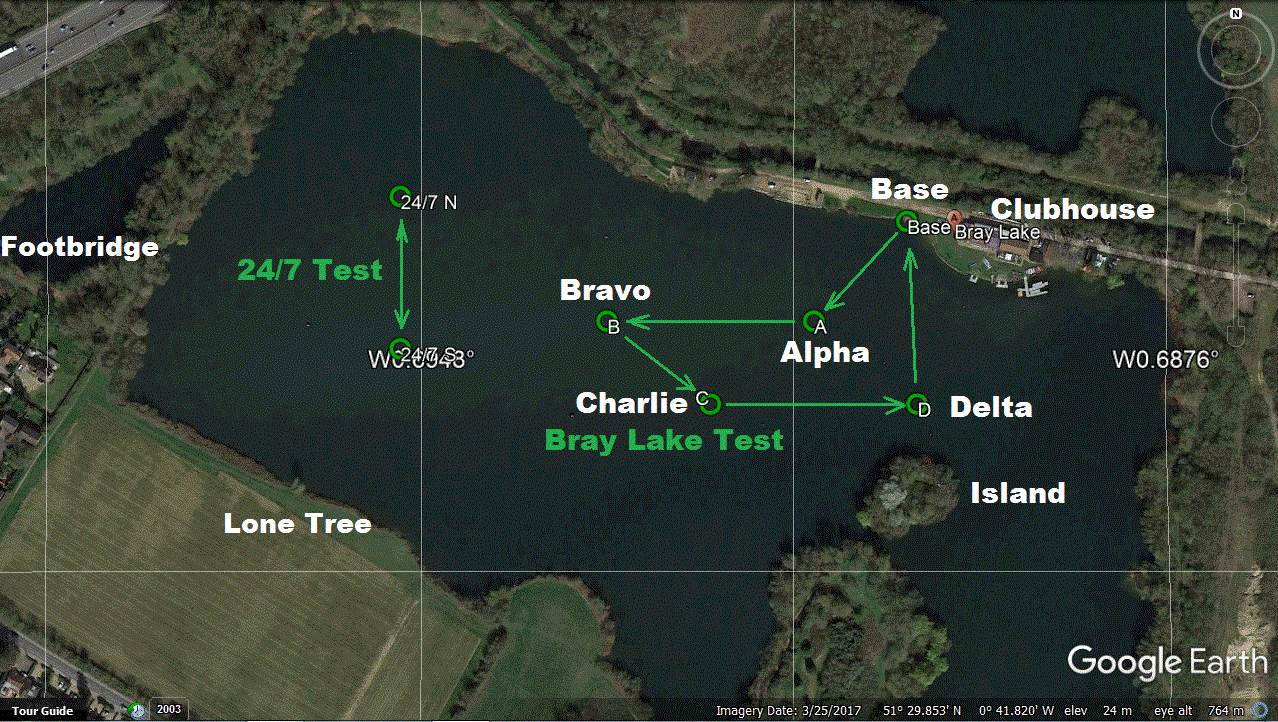
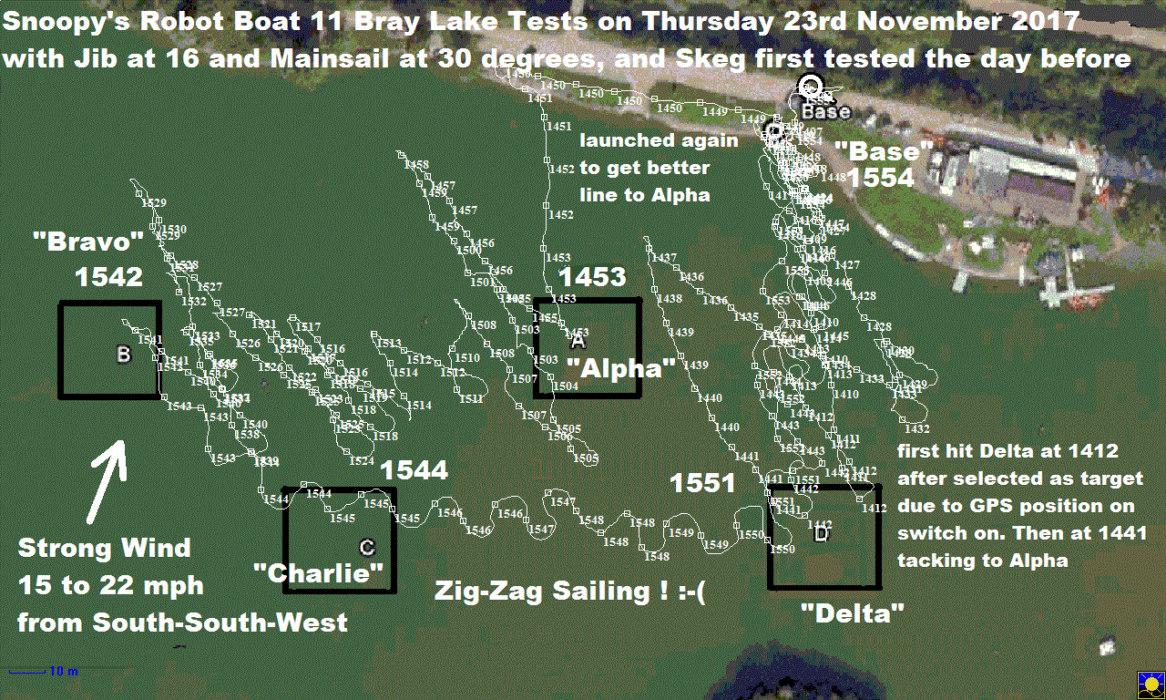
![]()
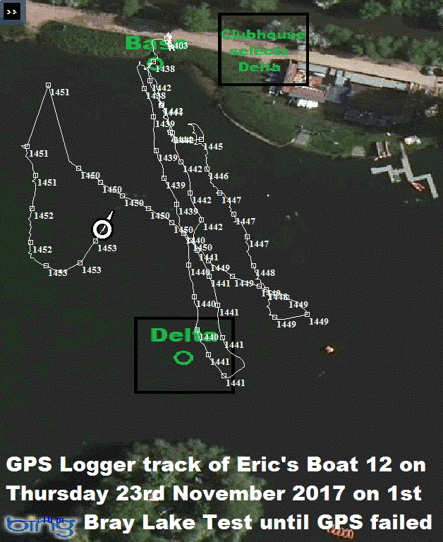
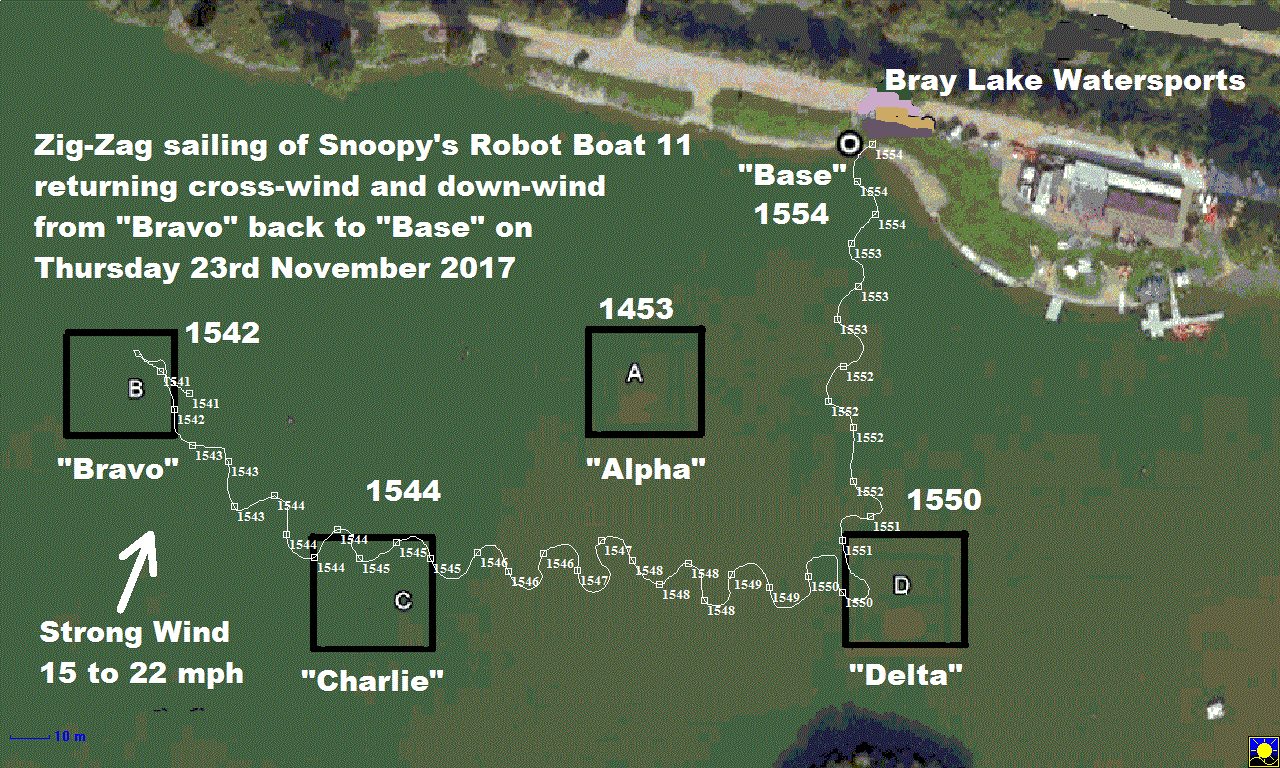
![]()
Tuesday 28th November 2017 (ONLY IN THIS BLOGX): For those interested, here are the results and GPS Logger data from the 6 hour test of GPS accuracy. Robin was surprised that there was no startup drift error, usually tens or even hundreds of metres. All positions, every second, for six hours, were within 0 to 3 metres: not unlike the accuracy he reported in May 2000, when Selective Availability (S.A.) was switched off. See www.GPSS.co.uk/sa.htm . The two files, AC281117.NME (just $GPRMC ) and AA281117.NME (All NMEA data) are zipped into aa281117.zip . Click on pictures below to enlarge or play the video.
 Wednesday 29th November 2017:
Just time to upload this video, before Dick and I do another test of Boat 11 at Bray Lake.
Snoopy's Boat is
HERE
! :-)
![]() Tuesday 5th December 2017: Zig-Zag sailing diagnosed and maybe fixed ? First a recent extract from Blog6, without some pictures,
then more about Eric's Boat 12:
Tuesday 5th December 2017: Zig-Zag sailing diagnosed and maybe fixed ? First a recent extract from Blog6, without some pictures,
then more about Eric's Boat 12:
Friday 1st December 2017:
The Youtube video is below, for those who want to see it.
Robin and June tool a very early trip to Slough today, for an 0630 hospital appointment:
full anesthetic to fit a plate into her broken wrist.
He took a printout of "Quebec" while he waited,
and saw suitable changes for new version "Romeo". Increased rudder gearing as function
of direction error, which should reduce zig-zag; The better TTS handling, such as "Left 15" more often can be left as is.
Not a software bug but just
a constant that needs to be changed: symbol MAXDERR = 120. This is the error angle
for full rudder. We will try 30 and test again. If it is too small, we may see over-steering, reflected in
a faster zig-zag rate of ~ 14 secs/cycle. We now have version "Romeo" ( AP28X2R.BAS ) in the test box,
and testing has started.
![]()

 June and Robin placed their food order before lunch: see the menu below.
However, Robin left before they ate, and returned to collect her mid afternoon. She was not
given a doggy bag, but they did get these Wallace and Vomit hats. THEN she dragged Robin out to The Dog and Partridge,
for the Royal Ascot Tennis Club Christmas Dinner ! :-)
Tuesday 5th December 2017:
Pictures of Boat 12 here soon. It is ready to sail against Boat 11 again ! Click on pictures to play or enlarge.
Saturday 16th December 2017:
Zig-Zag sailing fixed !
Boat 11 made
Brief Atlantic Attempt
yesterday :-)
Three small car clocks from China: less "clunky" test equipment.
They are now synched within a second or two, to GPS Time and Mobius time,
ready for the next Bray Lake Test.
![]()


![]()
 Saturday 30th December 2017:
The first video here gives the "bigger picture" of what happened on 15th December.
i.e. why Dick was already soaking wet before Snoopy made his
Brief Atlantic Attempt
:-)
You can see that Team-Joker take the engineering of their robot boats very seriously: there is no substitute for thorough and realistic testing, over what can be many weeks and months.
For those, particularly in Russia and Eastern Europe, interested in wider news from 2017, they can check out Robin's Christmas Newsletter , including new material near the end, previously secret :-)
![]() Thursday 18th January 2018:
Below is Robin's Christmas present from June being tested. We've still got products here to exploit, like the PocketCam. Click on pictures.
Thursday 18th January 2018:
Below is Robin's Christmas present from June being tested. We've still got products here to exploit, like the PocketCam. Click on pictures.
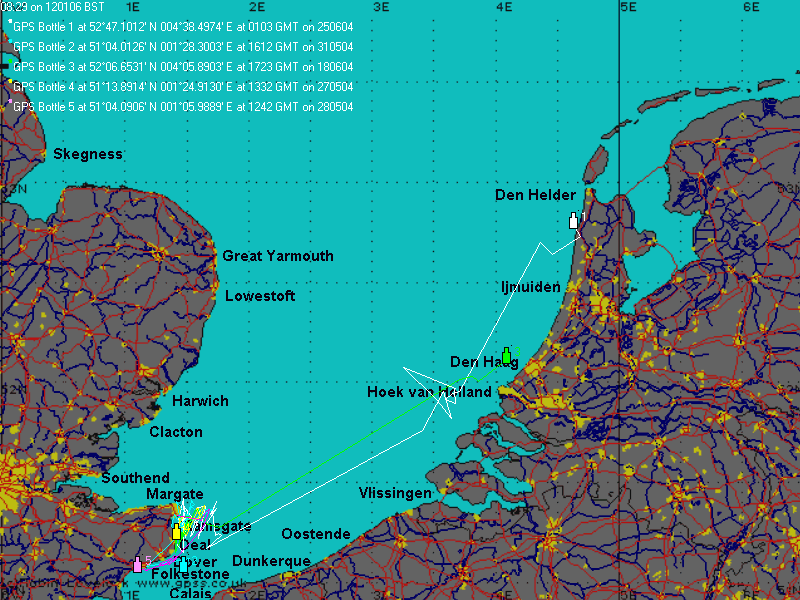 Friday 19th January 2018:
Click on the GPS Bottle tracking map to see details.
Here are some links and "pictures from the past" from an email within Team-Joker, discussing future use of PocketCam
to get pictures from our robot boats ...
Stuart may remember the first Bottle tracking project, in 2004, with the Opening at Margate:
www.gpss.co.uk/bottle.htm
.
After launch, we tracked the bottles across the channel, up the French, Belgium, and Dutch coasts, to Den Helder.
That was using my GPSS and SMS handling, exploiting GPS/GSM trackers from Germany.
This was when I got that TotalTide model and we understood the effect of wind and tide - still true today.
Years later, in 2011, the BBC funded their GPS Bottles project:
www.gpss.co.uk/bbcbot.htm
.
By then, Concox in Shenzhen China, provided the GPS Trackers using GPRS to China to update their tracking web site.
i.e. the only work was engineering the trackers into the bottles, with solar power - and, of course, TESTING !
Obviously, with a robot boat, the GPRS comms will work better.
Also, a camera might take more interesting pictures than from inside a wave trough.
My Blogs from a few years ago record ideas for trying PocketPal and then PocketCam - but there was never the time.
I suspect Stuart might be interested in repeating some of the capers we got up to with DuckCam at Windsor - with up to date kit.
e.g. DuckCam gave us pictures back, but, unlike PocketCam, you could not have a conversation from those throwing bread
at our radio controlled duck :-)
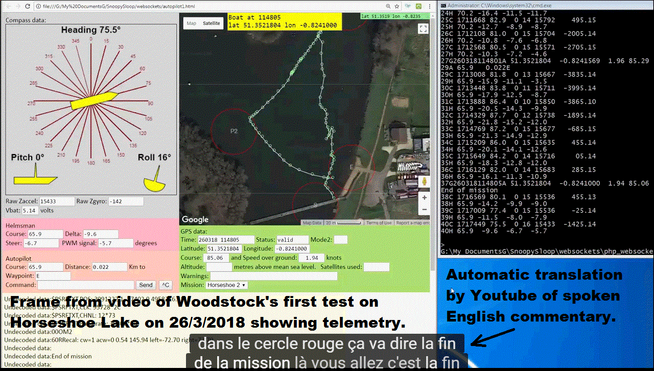
 Wednesday 28th March 2018:
First test of Woodstock on Horseshoe Lake, on Monday 26th March 2018,
in very light and changable (thermal) wind conditions.
Play the video to see the details, including conclusions. Youtube can provide automatic translation of the spoken commentry. Lots of new things tried out, including a Laptop on the shore to display telemetry data. EMC problems the day before meant that Dick's remote "drone" camera had to remain off. It was a great success, showing up problems to be fixed, but still completed the mission.
See "16th August 2017" above for Eric's Boat 12 doing a simple mission in similar light wind conditions.
Click on the picture here to expand the telemetry display. You can play the video below.
![]()
 Thursday 5th April 2018:
Yesterday, we took Woodstock out for it's second test on Horseshoe Lake - in pouring rain !
Woodstock is rapidly becoming Team-Joker's experimental test platform. Snoopy's Boat6 and Eric's Boat12
did this well, but Woodstock, being heavier, is a more representative test platform for new ideas.
It is heavier enough without solar panels, and of the same conventional bermuda rig, with jib and mainsail
boobs set to about 40 degrees - sorry booms - Fruedian slip. Horshoe Lake closing early, because of the rain,
and shutting gate to prevent cars being near base ( as at Bray Lake ) meant we thought of some new "equipment":
A fisherman's tent, to provide shelter and shade for the Telemetry Laptop and land-based cameras.
Use of remote video screens on the bank, was part of Eric's camera boat.
![]()
Wednesday 4th July 2018: Robin introduced Jonathan to Bray Lake with a test of Eric's Boat 12, but in very flat conditions. Robin forgot his wellies, so the launch involved throwing the boat in. We will try again when there is more wind. Click on pictures to enlarge.
![]()
Tuesday 15th January 2019:
Team-Joker, Woodstock, and Snoopy on Bray Lake on Sunday 13th January 2019. Click on pictures to play video or enlarge.
![]()

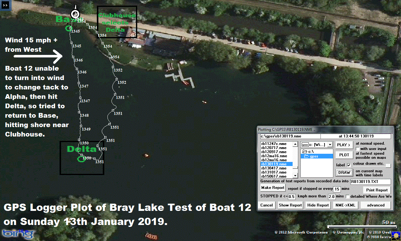
![]()
Monday 11th February 2019:
Snoopy's new boat 13, based on a plastic snow sledge, gets it's first Bray Lake Test. More work is needed: watch this space ! :-)
![]()
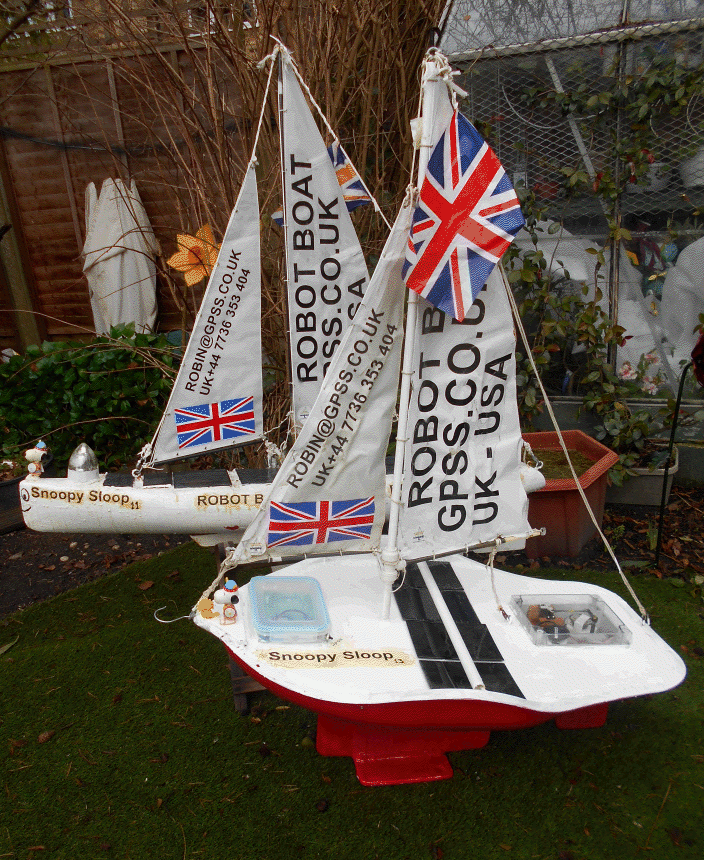
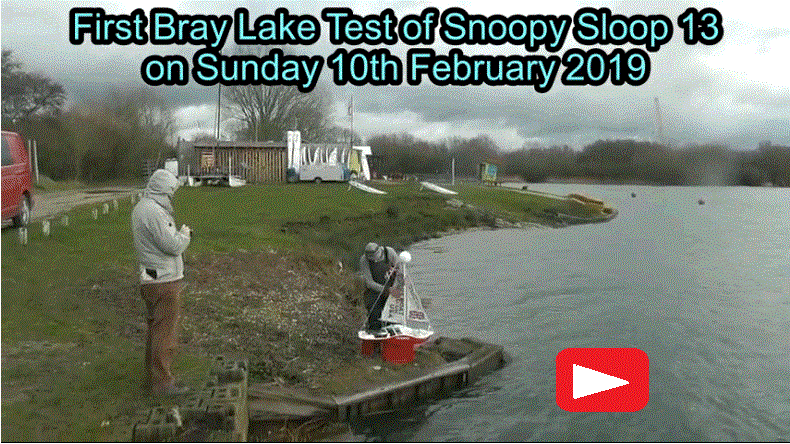
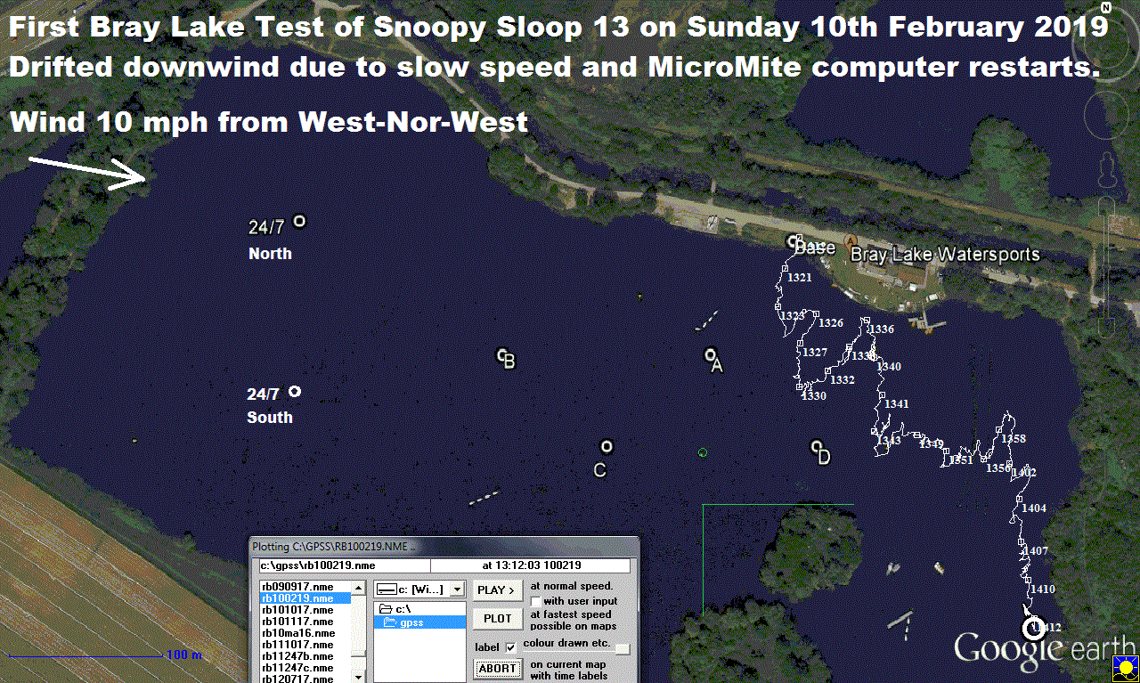
![]()
Saturday 2nd March 2019: Maybe Boat 13 can assist testing of Boat 11's SPOT Trace solar power supply on 24/7 duty ? More in due course. Priority "research" is in support of Snoopy Sloop 11, before this year's Atlantic Attempt. See end of Blog7 , including work on the I-GotU GPS Logger, in All Snoopy's boats since the first 2012 Attempt. Click on pictures to enlarge. Robin is testing a more recent product: the GT-730FL-S, having purchased two from Germany. This product MAY be a better long term solution than the home built GPS Loggers for Bray Lake Tests, or even - after software work and lots of testing - a longer term replacement of the I-gotU. But not yet: the I-GotU has worked well for years and has been "proven in Battle" - see Snoopy's 2015 Attempt :-)
Sunday 3rd March 2019: Boat 13 is now ready for Bray Lake, for use as a platform to test the SPOT Trace solar power suppy. The new GT-730FL-S GPS Logger (A) is now at the back ( see blue LED ) and set to record every 1 second. If power lasts, augmented by large solar panel and 4 cell 2200mAH NiMHd battery, 250,000 points is more than 4 weeks logger data. If set to record only every 1 minute, that increases capacity to last over 5 years. For anyone able to help Robin convert an CSV file exported from CanWay, there is an extract of a test walk in rb030319.csv. He is seeking just standard NMEA $GPRMC sentences to be plotted with GPSS on better maps or be used in his GPS Simulator. One of Robin's trusty Ardulog based GPS loggersalso sits near the front. But, before Boat 13 goes onto 24/7, it needs to do a Bray Lake Test, to see what effect adding those floats did ! :-)
Wednesday 6th March 2019:
The SPOT Trace is still working in the car. Today was daughter Samantha's birthday, and she flys
back from Mauritius tomorrow. So duty called, and Robin combined a SPOT Trace test with having
dinner at La Sorrentina. Adriano made a Tiramasu, with a lit candle, and a suitable "Happy Birthday Samantha" message :-)
![]()
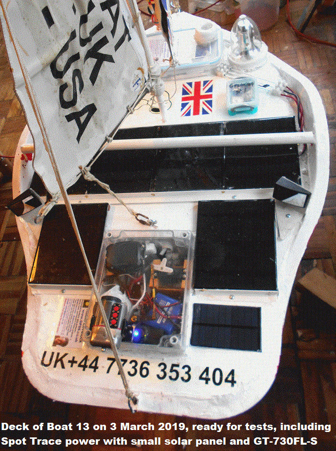
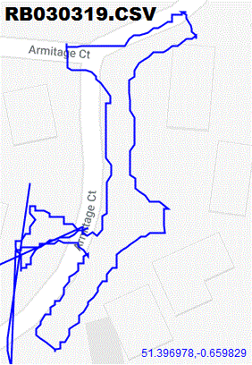
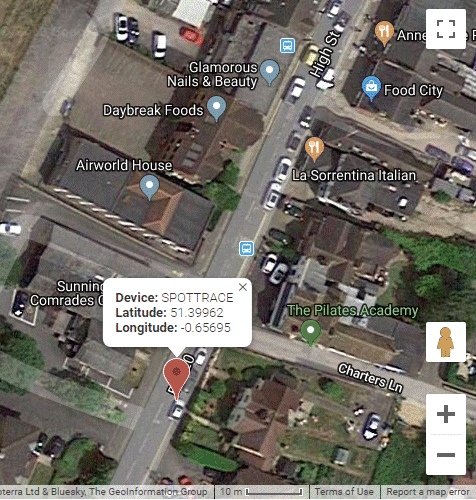

![]()
Friday 8th March 2019: Blog7 reports problems with the SPOT Trace tracker from Boat 11, being investigated in Robin's car. See SPOT Trace map to track the car. If SPOT works, it will become obvious where we are combining test, experiment, and fun ! Robin may put things like his Pocket Cam tracker and Mobius camera, onto Snoopy's little Affinity boat, seen on Eric's Page and these pictures below, including new "artwork" and radio control. Click on pictures to enlarge. June brought back a present for Robin from Mauritius: let's see if Robin can squeeze the electronics into that ! :-)
 Tuesday 12th March 2019:
Play the video to see Snoopy enjoying the long weekend at Center Parcs in Longleat Forest,
starting the Friday.
This was mostly the Lovelock family having fun, but GPS technology got some testing too ! :-)
We DO have a problem with the SPOT Trace tracking stopping. Voltage remained high, dropping little
below 6.50v in two hours of driving. SPOT Tracking started OK whenever the car was moved after over a day
being stationary. This included driving the car down from the car park to our chalet 933 on Monday.
BUT when we got home, Robin saw there had been no other position reports. He had to press the "start"
button again, and see two flashing green LED.
This is a much greater concern than confirming that the small solar panel can cope.
We might add a watchdog timer, to "reboot" the SPOT Trace, to attempt to fix the problem, but first we should diagnose it. If we can reliably repeat the fault, we can better see if any solution works properly. Maybe the problem is a bug in something like the SPOT Trace firmware, already the latest version. This is where technical help would help ! :-)
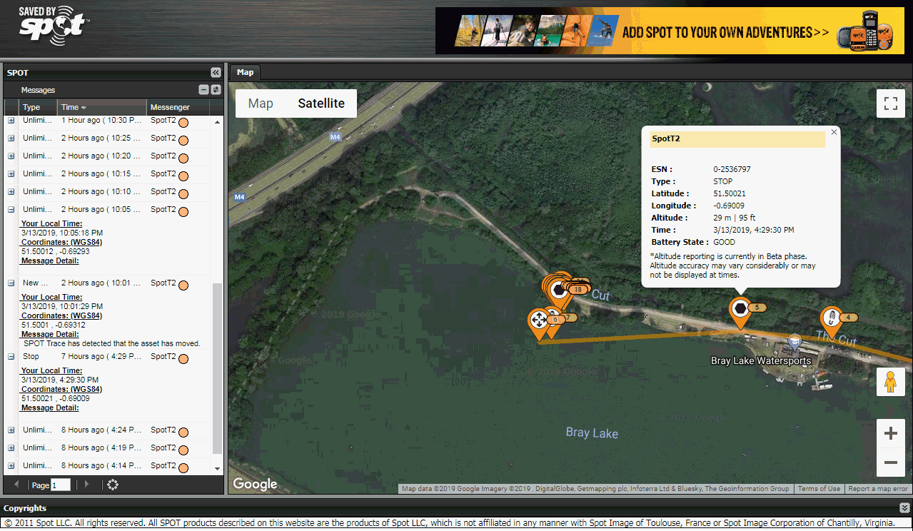
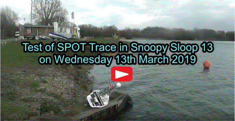 Wednesday 13th March 2019:
Today Snoopy Sloop 13 was put onto 24/7 duty at Bray Lake, to test the
SpotT2.
tracker, but it was soon discovered that the SPOT Trace had stopped reporting
after arriving at Bray Lake. At least this tracker is showing
the same, repeatable symptoms as
SpotT
being tested in Robin's car.
The 11 minute video shows all sorts of other things happening,
like the earlier Bray Lake Test being abandoned when one of the floats
fell off the boat. The silicon sealant obviously does not work
well as glue on the plastic hull ! With both floats removed,
the boat sailed out to 24/7 duty OK. It has the text-to-speech (TTS)
speaking loudly, and consuming power. It also has a Mobius video camera that may
hold some interesting clips from the first hour, before it stops.
Tomorrow we will see if Snoopy Sloop 13 is still on 24/7.
If so, we may recover it and switch on
SpotT2
again, before putting it on 24/7 again.
Options for recovery including a Clubhouse "Rescue",
or use of Snoopy's Windmill boat.
Thursday 14th March 2019:
BUT AT 2201 (Yesterday)
SpotT2.
STARTED REPORTING AGAIN ! Click on the picture to enlarge.
This behaviour looks hard to explain. Robin recalls a means of adjusting SPOT movement sensitivity.
At least it should be easy to recover today and re-launch onto 24/7 in the morning, to gather more information.
June and Robin, armed with his voltmeter, expect to reach Bray Lake soon after the rain passes at 1100.
They will recover the Mobius camera and GPS Logger - expected to hold the whole 24/7 track.
Probably put Snoopy Sloop 13 back onto 24/7 after giving it a good shake and making sure the
SpotT2.
is working.
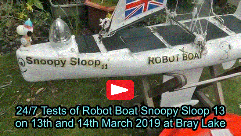 Thursday 14th March 2019 evening update after Robin and June visit Bray Lake:
It's going to take some time to edit, process, and upload the video, but for now, here are some frames
you can click on the enlarge. Sorry to those waiting for answers to your emails, but it will be better
for Robin to include the answers here. e.g. before designing a "system" like a robot boat, it is wise
to think how you will test it, and make that influence the design. e.g. being able to test sub-systems
and the total boat system at one's home and on Bray Lake, rather than only at sea.
The final video is expected to be about 30 minutes, including significant clips from the Mobius camera.
e.g. when it capsized, righted itself, but got the logger wet, and then the Mobius.
In short, it was an extremely useful day, and I hope the video is both entertaining and educational,
for budding old engineers.
Click on pictures below to expand :-)
Friday 15th March 2019 after
UNEDITED 33 minute video
uploaded:
You can wait for the
edited version
, but don't hold your breath
NOW DONE :-)
Important extract: "Yes Roy, I've made a checklist:
1) Find Boat Snoopy Sloop 13 (done 1145). 2) Recover boat. 3) Remove Modius camera to take home. 4) Remove GPS Logger
to take home. 5. Measure voltage of main Autopilot 5v supply. (Good 5.12v, 5.09v at 1200).
6) Measure voltage of SPOT Trace. (Good 6.33v ). 7) Give SPOT Trace a shake (shook boat).
8) Check on smartphones SPOT Trace 1 (in car) and Spot Trace 2 (in boat). (Done at 1230 "9 hours ago").
9) Put boat back on 24/7 test ? (Done - watched it capsize and right itself a few times !).
Then extras added to list: 10) Go to Halfords to change rear brake bulb. (had a spare and did it myself !)
But then saw boat had come ashore, so went back to Bray Lake.
11) Recover boat from brambles near Segway Cabin - difficult !
12) Home by 1455 with LOTS to do :-)
 Conclusions so far:
Important work needed before the 2019 Atlantic Attempt will be to fix SPOT Trace.
This will probably, as has been done before, be by asking SPOT Service for help.
Quicker help may be available from my wider circle of overseas "Team-Joker" friends,
who have a SPOT Trace.
I must try use of the "SPOT Trace Sensitivity Console". But the version on my PC is "20150805",
and I must be careful with differences in version. Dick's idea of putting the SPOT Trace into
"Docking Mode" was rejected years ago, because of the 200 metre movement threshold.
See my words above designing a "system" and testing. BUT, since, as Terry says, SPOT Trace
was not intended for robot boats use, we may find a work-around, such as decreasing the 200m threshold.
There is another approach which I dislike, because it raises the SPOT Air Time from over 100 GBP per year
to even higher: what SPOT call "Extreme tracking". The repairs and modification on Boat 13 can also be done,
so it is available for testing and fun. BUT the bottom line is that my time for robot boat work is VERY
limited, so I must prioritise my time on things that contribute to the next Atlantic Attempt this year.
Maybe my old
Bigger Picture
page is relevant ? Yes, as it happens, it is, and I'm now engaged in a number of other "charitable activities".
But I should add that "fun" activities such as the weekly Pub Grub with wise old engineers like Richard and Stuart,
and Team-Joker founder member John, often give me best examples of "lateral thinking", "new ideas", and "Engineering Wisdom" !
Click on the picture to enlarge: Roger, Richard, Stuart, Dick, and John :-)
Saturday 16th March 2019 from Robin:
The video above is now the
edited version
.
Earlier today I posted the above information onto the
Microtransat Google Group
, but this forum seems to get few postings. Good if guys can contact us direct by email anyway, to gpss@compuserve.com
or robin@gpss.co.uk.
Click on the pictures to enlarge and read: how to switch on SPOT Trace; Checking the settings: Report every 5 minutes
with docking mode OFF; Movement sensitivity. I now have a triplicated online backup of their Spot Trace User Guide in
SPOTTUG1.PDF
. Yes, I'll take the risk of revealing the Authorisation Code. Earlier movements to my back shed triggered reports.
The
SpotT
is now in the car, ready for more road tests.
Voltage was 6.46v at 1115.
Work has started on Snoopy Sloop 13.
Sunday 17th March 2019:
Click on pictures to expand and read the text.
Dick will be pleased that the two floats will be easily detachable, held to the hull by an aditional long carbon fibre rod,
pushed through both floats and the keel. This will permit Bray Lake Tests with and without floats, for comparison of speed.
Here is Boat 13 after bolting two sheets of Homebase aluminium, 50 x 25 cm, bent at 90, either side of the old keel,
with extra wood at bottom. This is bolted to a Homebase plastic kitchen chopping board, 29 x 45 cm.
The keel is now 38cm deep, compared with the original 25cm. We can put back the 0.5 kg lead sheet if needed.
One photo is after Isopon P38,
before smoothing and painting, with a spay can of Hammerite "Direct to rust metal paint smooth red".
We will see how well it lasts. Yes, that's the boat in Robin's garage, with "welcome home" message for June,
who keeps her car there.
Now for today's trip out with June in the car, to go somewhere nice - and test
SPOT Trace
;-)
![]()
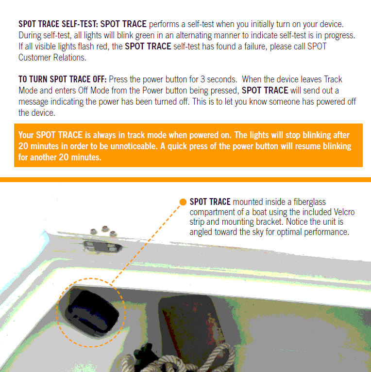
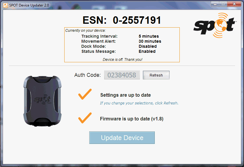
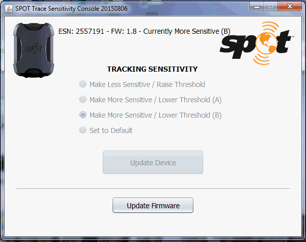
![]() Sunday 17th March 2019, after the trip:
Click on pictures to enlarge. What lovely coincidences, and what a great 6 hours out, from 1315 to 1915 back home.
We had decided to visit Asthall Manor, open for the day for charity, under the
NGS
.
Then we realized it was only 20 minutes further to where our friends Spitfire was.
First the bad news: the SPOT Trace did not restart it's reporting after the stop at Asthall Manor.
But in Robin's book this is good news: we are reliably recreating the fault, by a simple car journey.
If we make a change to rectify the problem, it should be easier to see if it fixes it !
What a coincidence in the name of that farm ! Yes, I know what you will say, Steve: "Wrong Tail Number !" :-)
Sunday 17th March 2019, after the trip:
Click on pictures to enlarge. What lovely coincidences, and what a great 6 hours out, from 1315 to 1915 back home.
We had decided to visit Asthall Manor, open for the day for charity, under the
NGS
.
Then we realized it was only 20 minutes further to where our friends Spitfire was.
First the bad news: the SPOT Trace did not restart it's reporting after the stop at Asthall Manor.
But in Robin's book this is good news: we are reliably recreating the fault, by a simple car journey.
If we make a change to rectify the problem, it should be easier to see if it fixes it !
What a coincidence in the name of that farm ! Yes, I know what you will say, Steve: "Wrong Tail Number !" :-)
![]()
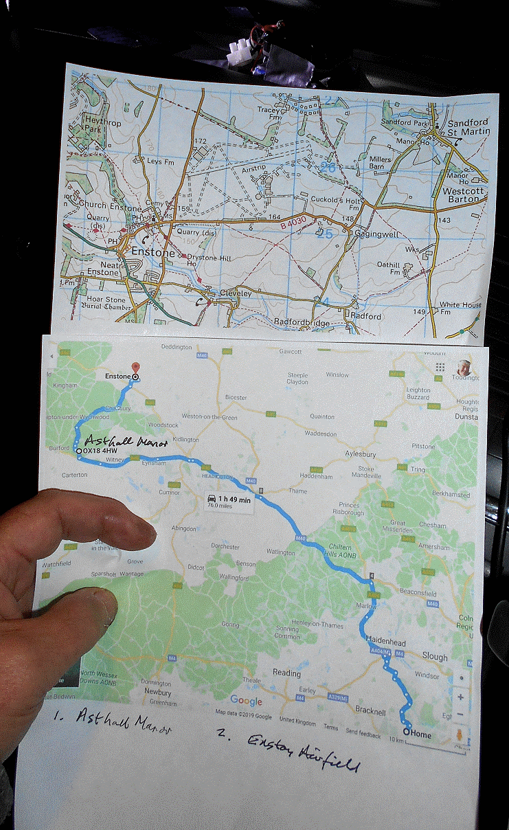
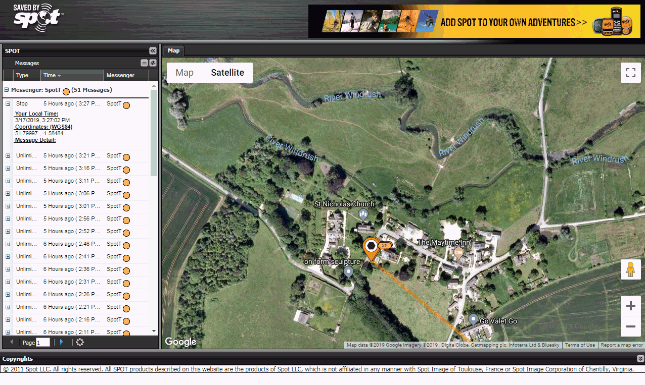

![]()


![]()
Monday 18th March 2019:
A detailed email was sent to SPOT Customer Service at 1019. Hopefully it will reach the right Technical Support guy.
Meanwhile, we now have two SPOT Trace in the car for test and comparison:
1)
SpotT
for Boat 11, with it's Solar Panel and rechargable 5 AA cell NiMH pack.
2)
SpotT2.
which now has reverted to the reccomended 4 AA cell Energizer batteries.
Both showed very similar voltages at 1345: 6.45v and 6.41v respectively.
This was when Robin and June took a trip out, including over a 1.5 hour stop in Tring, returning at 1925.
Both SPOT Trace gave the same, correct, tracks. Earlier, more work was done on Boat 13 and this will be reported soon.
Click on pictures :-)
Tuesday 19th March 2019:
Click on pictures to enlarge.
Boat 13 is practically finished, and here it is in Robin's bottom pond: 11.5 kg without floats and 0.3kg lead weight,
needed if floats added. With floats it's 12.7 kg. Bray Lake Tests with and without floats will be interesting.
e.g. stability and speed ? Soon June and Robin were off for
roof
and
garden
stuff - and another SPOT Trace road test ... and both
trackers
worked well, showing us leaving home at 1355 and returning at 1745, with stops at B & Q, Squires, and Sunninghill.
Wednesday 20th March 2019:
SPOT Trackers still good after pub grub trips - needed to discuss ideas like SPOT test rigs based on motorised pulleys or model train sets :-)
Sunday 24th March 2019:
SpotT
FAILURE, after several days of car tests, with both trackers giving same good tracks. Today SpotT gave it's dailey Status Report at 1118, then only one,
final, "New Movement" report at 1243. Only SpotT2 reported the rest of the day's track, south of Guildford and back. Voltages at
2000 were SpotT: 6.41v; SpotT2: 5.83v. We will see if SpotT manages a Status Report tomorrow !
Monday 25th March 2019:
NO, still nothing after a trip to Southampton and back ! Power wiring resoldered; interruption of power no effect; pressed ON button at 2030. Working ! :-|
Tuesday 26th March 2019:
DIAGNOSIS ? Temporary power loss, such as poor spring contact, or bad wiring, causes the SPOT Trace to enter the "Power Off" state.
This requires the button to be pressed, to get green flashing lights. Power resumption causes only a brief red flash.
The ideal solution would be change of settings, or firmware, to ensure powering up into the "ON" state. This covers things
like temporary loss of solar power. A timer operating the switch under the button, as we did for the old SPOT Messenger,
could be considered, but in Robin's opinion that's "messy". No reply back from SPOT Support, after over a week since the email of 18th March.
SpotT2
has been rewired onto the same type of small 6v solar panel, and a single 5 AA cell NiMHd pack. Voltages of
SpotT
and
SpotT2.
were 6.40v and 6.74v respectively, at 1220. We will see what more car testing reveals.
Thursday 28th March 2019:
SpotT failed again, and not SpotT2. SpotT did not restart after STOP near West Byfleet. Switched ON after checking firmware latest v1.8.
![]()
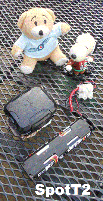
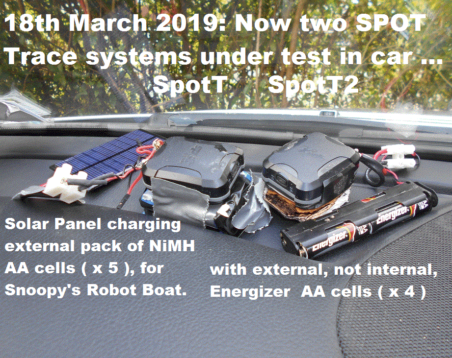
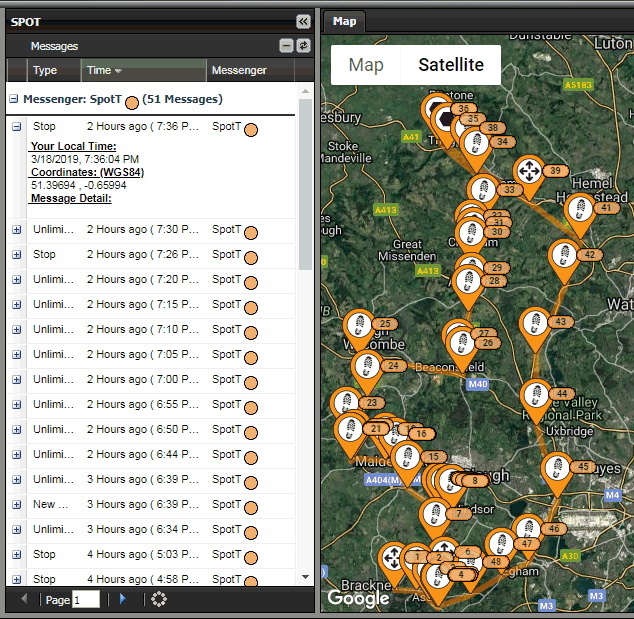
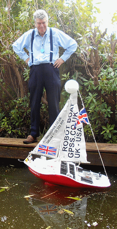
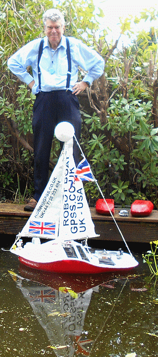
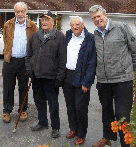
![]()
Friday 29th March 2019:
FAULT WAS POOR SOLDERING ? Closer inspection after unsoldering the power leads into SpotT revealed
things like no solder had stuck to the gold printed circuit pads. Also it was very difficult to
get solder onto the bolts. When re-soldering, two brass rods were also used, in addition to the bolts.
Click on pictures to enlarge.
We will see what road-testing reveals !
Saturday 6th April 2019:
GOOD NEWS.
SpotT
Still OK after 7 days of road tests.
SpotT2
failed after weeks of being OK, so was also re-soldered and the springs removed.
Sunday 21st April 2019:
SpotT
Still OK :-)
It was soldered back into Snoopy Sloop 11 and restarted at 1015. Terminal block is a monitor point.
SpotT2
remains in the car for now.
Saturday 15th June 2019: 7 weeks and both SPOT Trackers are still running ! SpotT in Snoopy's boat giving it's daily status report at 1024 BST.
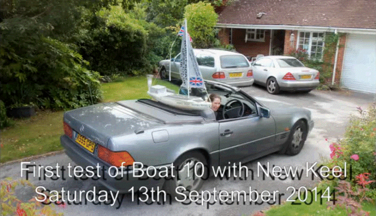
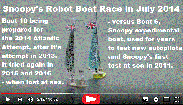 You may wish to play
Testing Snoopy's Robot Boat Repairs
- Snoopy's first Bray Lake Test with the new keel on boat 10, back in 2014.
Or just click on the pictures. Check out the automatic youtube subtitles, translated into your language.
Experiments with Boat6 in July: see Recce, Compass and Software pages. Play the July 2014 video of Snoopy's Robot Boat Race to see how well Snoopy's 2014 boat 10 did against the smaller experimental boat 6.
That's Robin, on the left, sat on the bank of Snoopy Corner, watching Snoopy Sloop 10 on 24/7 test (right), filmed by experimental Boat 6.

Below is an early frame, from the Mobius video camera. Here, Snoopy returns to Base, near the drain and Robin, Snoopy's chauffer :-)

There have been
visits to this page counted by
Digits Web Counter since 18th February 2016.
© 1991-2016 Robin Lovelock. Please credit www.gpss.co.uk if you use material from any of these pages. Thankyou.