


This page too technical ? Then see the
"Recce" Page of us having fun with the experimental Boat 6 filming others.
Play the
July video of Snoopy's Robot Boat Race - see how well
boat 10 did against the smaller experimental boat 6.
See the Movie ! Watch the 10 minute
Video of Snoopy's Compass-Steered Robot Boat - July 2014 !
See "2014 and the Devantech CMPS10 Tilt Compensated Compass Module" at end of this page,
and Video

 You probably reached this "Compass" page from the
Design page linked from my
Robot Boat page.
Click on the links above to know what this page is all about:
possible use of a compass within future robot boats.
Most of this page was written in 2013, and relates to a particular non-tilt compensated product.
However, in 2014, I found other products, and I've added new sections at the very end of this page.
The new video above, shows one of Snoopy's experimental boats working with a new computer and tilt-compensated compass.
When making a robot boat, an electronic compass is the obvious solution for steering, even if GPS is used for navigation and to decide what direction to steer. You will see those were my first thoughts when I started this hobby project. See "early thoughts" at the bottom of Progress in 2008 to 2010.
However, until 2013, I never got round to trying a compass. In the early years I worked on a wind-vane, then several years ago, adopted "only GPS" as the steering solution. The autopilots used in boats 6,7,8,9 and 10, all use the GPS "true heading" for steering. But, in the summer of 2013, I started experimenting with the Sparkfun Honeywell HMC6352. There was an outside chance that it might find it's way into a future boat.
The reason for my taking an interest in a compass, was the possability of reducing still further the power consumption of the autopilot. e.g. the GPS consumes 35mA compared with only 1mA for the compass. Maybe the GPS need not be switched on all the time, if it is not used for steering ? Lower power means less solar panels, a smaller boat, and - maybe - a less expensive one.
The compass would sense where the boat is pointing, for the autopilot steering. Our simple GPS solutions use, instead, the direction the boat is moving - which is not the same thing. Things like the tide can "confuse" the autopilot. We can live with this design limitation, but, if we wanted to perform a sailing mission such as "sail around the Isle of Wight" - we would need to have an autopilot that would handle the tide better.
Thanks to Jim on the PICAXE Forum Robot Boat Thread I found the HMC6352 Compass Module. It seemed to be just what was needed. More detail is on that Thread above. Thanks also to Thierry, for suggesting an alternative and his MAG3110 thread describing the software.

 I got three of HMC6352 Compass Modules in early August 2013, and that PICACE Forum thread above
gives details of getting simple PICAXE test programs working. We now have an autpilot
being tested, which uses both GPS and a gimbal-mounted HMC6352 compass.
The main problem was the huge "tilt errors", since this compass chip is not "tilt compensated".
The compass was therefore mounted on a gimbal.
Below is the HMC6352 Compass mounted on the gimbal made from soldered brass strips and tubes. The weight is a 2oz lead weight from a fishing tackle shop, and the plastic enclosure is a 0.5L "Whitefurze" food container from a hardware shop. To the left of this is the Picaxe AXE024 servo controller, 5v battery pack, and Text-To-Speech unit, driving the loudspeaker - kept well away from the compass ! :-) By 18th August the autopilot was being "road tested": see the road test utube video. By 1st September, we had started "water testing" the compass-autopilot in boat 6 on Bray Lake (see left).
 Even if we get the system to work well, the compass may not be adopted for use in future boats. e.g. decreased reliability ?
I would describe the current work as "research" rather than "development".
The main role of our experiments is to gather knowledge that may enable us to improve the GPS-only steering. e.g. the GPS steering control loop is 7 seconds. Maybe this could be made faster, even if not as fast as the 10Hz+ compass-rudder control loop. e.g. the autopilot "rudder trim" logic, which attempts to balance the boat as it sails.
The compass steered the boat around the course on 12th, 13th and 20th September, but in light wind conditions. See the GPS plots below. It seems the gimbal has reduced tilt errors, but what remains explains the "landing error". If the boat tilts 30 degrees, the tilt error could be more than 30 degrees in direction, but with the gimbal it is nearer to 10 degrees. see the picture on right, for the messy inside of our gimbal: the remaining tilt error is probably due to the "springyness" of the wires, connecting to the chip, rather than "stickyness" of the two bearings.
 On 27th September the compass was removed from boat 6, and our experiments are now directed to improvement to the GPS-Only steering logic.
We have also started to experiment with possible use of a HK401B Helicopter Head Lock Gyro, combined with the steering logic.
See picture right, and "Better steering stability ?" below.
Conclusions from these experiments with the compass are:

 bad thoughts in 2013...
Before testing a gyro, in the steering path between picaxe computer and rudder servo,
we will try some simpler ideas. We want to make the boat more
stable in direction, under different wind conditions. e.g. reduce "weather helm",
turning the boat towards the wind.
The simplest idea is to pull in the jib even more. This will be tried soon.
These pictures, left and right, show a simple idea also to be tested. Two fixed "tilt rudders"
will normally be clear of the water, when the boat is upright. Suppose that wind from the
left (port) side, is strong enough to induce weather helm, turning the boat to the left,
the boat will be tilting to the right: maybe 30 to 45 degrees or more. The right hand
rudder then dips into the water, and has been adjusted to do a "turn right" to compensate.
This simple assembly bolts onto the back of boat 6, and we can experiment by adjusting
things like the angle of the two rudders.
in 2014: it was simpler to "balance" the boat. e.g. mast position. But these old thoughts may amuse you :-)


Tests on Friday 20 Sep 2013: Both Compass-Steering and GPS-Only-Steering OK in low wind. "Landing Error" due to remaing compass tilt error.

In June 2014, I discovered the Devantech CMPS10 Tilt Compensated Compass Module and ordered one, for possible future experiments. It seems to meet my requirements of being a sensible price, and has options of using it via serial or I2C communications. Software changes would be needed, but it looked well worth checking out. I did ! See below :-)
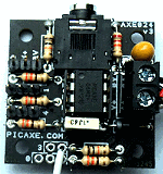
 For years I've used the PICAXE Servo Driver (left), based on the 08M2 chip, but this has always been a squeeze, to get the Autopilot
Program into the 2KB of program memory. When working on something experimental, like use of a compass, or wind direction sensor,
I usually have to strip out some of the code to make space. I'm also limited to what gets spoken by the Text-to-Speech.
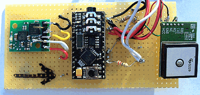
In June 2014, I got a PICAXE "28X2 Module" (not to be confused with the 28X2 chip, which has different pin connections). Further below, on this page, is part of a page from the PICAXE documentation. On the right is a picture of the Picaxe 28X2 Computer (centre) being tested with the Compass (above arrow) and a Skylab GPS (right). The arrow shows orientation of the compass.
 The whole of my 08M2 Autopilot program runs on this 28X2 Module,
with practically no software changes, but with 2KB of memory free - instead of only several bytes ! :-)
I got two more of these, for experiments leading to next year's boat. It did not take long to get the
CMPS10 Tilt Compensated Compass working with the 28X2 based computer.
Boat 6 had it's first test on Bray Lake, on 1st July 2014, with the 28X2 computer and compass based steering, but with the same
Globalsat BR355 GPS that has been used in all of Snoopy's boat for years.
 I was able to drastically reduce the power consumption of the compass, from less than 20mA to an average
of less than 1mA, by using the Picaxe program to switch on the compass just before it is read, then switch it off again.
If it is only switched on for 0.1 seconds, in a rudder servo control loop of say two seconds, that only 5% of 20mA.
i.e. 1mA - not worth worrying about ! :-)
 I've been experimenting with different GPS products, looking for one that will reduce power consumption. I'm looking for
low average current drain when the GPS is tracking, but also for a fast startup - which means the GPS could be switched off
for some of the time, like the compass is now. Models that I'm looking at, include the more recent Globalsat BR355-S4,
the Skylab SKM53 (based on Mediatek MTK3329), the Mediatek MTK3339 - within the "Ultimate" (see left), and the Telit Jupiter JN3 (John gave me four, on the right).
See the
Video of JN3 GPS Tests.
 The Globalsat G-Star IV (BR355-S4) was the last GPS to arrive here, all the way from Taiwan - but it did not disappoint !
I was amazed: it started tracking within seconds, and very accurate,
including speed - drops to 0.0 when you stop! Next step was to try the Picaxe switching it on and off from the autopilot program.
That went quickly too: just one transistor needed, so not to overload the Picaxe pin, only rated at 20mA.
The "tea-tray test" was done well, with the GPS typically switching off for a few seconds compass-based steering,
then only needing to switch on for what seems a couple of seconds.
I've now removed the magnet (so not as to effect the compass).
It's tempting to put it in Boat6 to test on Bray Lake ! Boat 6, our yellow mobile laboratory, is taken for an occasional "Bray Lake Test", to checkout the latest version of the GPS-28X2-Compass autopilot. The software will need "tuning", with things like how long the boat can remain on compass steering, not looking at it's GPS, without risk of "overshooting" the waypoint. e.g. 30 seconds if more than 50 metres from it, 10 seconds if more than 30, but only 5 seconds if closer. Currently, the program does not switch off the GPS unless more than 30 metres from the waypoint. Lots of testing and tuning is needed, but it seems we should at least halve the power consumption - maybe better.
We now have three working Picaxe 28X2 - CMPS10 Compass boards:
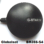 1. One in Boat 6, using a Globalsat BR355, for Bray Lake tests of compass-based steering, and "tuning" of the software.
2. One now based on the G-Star IV, with GPS power switching to reduce power consumption - and test the effect of this.
3. One for testing with the other GPS types we have, with slightly modified versions of the software, for each GPS type.
Several things are now competing for priority:
a) testing the new G-Star based autopilot - tradeoffs between power consumption
and autopilot function - particularly at short range.
b) trying battery backup
and/or sending sleep mode commands on the various GPS products.
c) Solving problem (below), related to the MTK based GPS products.
 On the left you see that one of our "tea-tray" systems, used to checkout the effects of power switching of the GPS.
The iPAQ has been added, taking the same signal from the DIN socket, as that fed to the Picaxe 28X2, and running Robin's
GPSSpc GPS Software for the Pocket PC. This means we can see any "spurious" GPS positions,
after powering up the GPS, which could cause the Autopilot to switch to the wrong destination waypoint. e.g. if the
spurious position were in the Atlantic, the Autopilot might aim for the Microtransat start or Finish lines,
or the Azores. The GPSSppc mapping includes "house-level" detail in our test areas, such as near Robin's home or at Bray Lake.
Less detail is included elsewhere in the World, but we don't need to know exactly where the spurious positions are ?
If we see a pattern, such as the place of GPS manufacture, we can easily record the data on the iPAQ for later analysis.
The latest version of the AUTOPX1.BAS Autopilot program now speaks additional data to make testing clearer near home or at Bray Lake. e.g. "at waypoint Robin's front door" or "at waypoint Alpha" instead of just "at waypoint". e.g. "Steer 025 to Richard's lamp post" instead of just "Steer 025". Also, the Autopilot now only says "Ahead" if within 2 degrees of the correct direction, instead of 5 degrees. This seems accurate and stable - if not too close to steel car bodywork. This version of the Autopilot is in Boat6 ready for Bray Lake tests, as well as in our tea-tray systems.
 The following is for those giving detailed technical help to Robin ....
At the time of writing this, the BR355, BR355-S, and JN3 based versions work OK (software programs AUTOPX1.BAS aand AUTOPJN3.BAS respectively).
There is the same undiagnosed problem with both the SkyLab MTK3329 and Ulimate MTK3339 based versions (AUTOSK1.BAS and AUTOULT1.BAS):
There is no problem with switching them from default 9600 to 4800 speed, using $PMTK251,4800*14 (to rule out Picaxe timing problems),
and the expected Time is received, after the $GPRMC, not long after power on. However, instead of the expected 5123.81 after the ,A,
(given many tens of minutes for the GPS to start tracking), we get unexpected data such as repeated "3,1224", with the occasional
"5123810" (without the decimal point). For reference, a typical $GPRMC sentence should be:
$GPRMC,064951.000,A,5123.8160,N,00039.1234,W,0.03,165.48 ... etc (the test programs show 7 characters after $GPRMC and ,A, ).
 We can now add servo power switching to our list of goals achieved. Our experimental AUTOPX1.BAS program switches 5v power to:
1. the compass, reducing it's typical consumption of 20mA to nearer 1mA: so no penalty in adding the Compass to the autopilot.
2. the GPS, reducing consumption from typically 30 or 40mA to half that, or better: this is where the main power saving is made.
3. the servo, reducing the stationary consumption from 10mA to typically half that or better: every little helps ! :-)
The servo we are using can move between positions in typically 0.5 seconds, so if the steering servo position control loop is every 1 second, this is reducing the power consumed by the servo. During movement of the servo motor there are "spikes" of perhaps 100mA, but these are short-lived and so not a big contribution to overall power drain. Lots of testing is needed on this power switching of the servo, to ensure there are no detrimental side effects, such as ability of the boat to hold it's rudder position when needed. However, so far, no such problems have surfaced.
I've just set up a new page, for those interested in the software for Snoopy's future autopilots. More advantages of the Picaxe 28X2 are surfacing, such as trig functions SIN, COS, ATAN and SQRT. It should not be too difficult to replace some of our crude approximations by more accurate ones.
Remember - these new bits and pieces are for possible inclusion in boats for future years: Snoopy already has a reliable set of electronics in boat 10, intended for the 2014 attempt ! :-)
First Bray Lake Test, of Picaxe 28X2 Computer + CMPS10 Compass, was on 1st July 2014, and went well.
See the Video of Snoopy's Compass-Steered Robot Boat from 1st July 2014.

Details of the Picaxe 28X2 Module ...
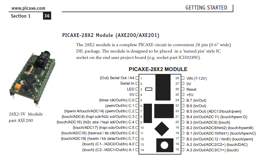
Above picture only is (c) Revolution Education Ltd.
First "walking test" of the Picaxe 28X2 baased Autopilot in progress ! :-)

Here are some thoughts, in June 2014, before I found the CMPS10 Compass....
These thoughts were after chatting with a new friend, who may prefer to remain anonomous :-) I'm hoping that he or someone else, might find or make a "Compass-GPS Module" that would make it extremely easy to integrate a compass into the autopilot. It's possible the product could be used for completely different applications, such as hand-held Direction Finding products for tracking wild life.
 The Module includes the important "compass" function, and that's where most of the work in developing the product would be.
i.e. use of the appropriate chip and software to generate a tilt-compensated magnetic bearing, to be sent at 4800 baud,
in a suitably simple text format (e.g. simplified NMEA $GPBOD ?) on the same serial output as used to pass the GPS
data (e.g. only NMEA $GPRMC every 1 second). A simple on/off signal back from the autopilot computer, could switch off
the GPS, to make a big reduction in power consumption (e.g. from 40mA to less than 5mA?).
If the $GPRMC sentence is output every 1 second, the $GPBOD sentence might by output 0.5 second later, to make it easy for crude computers such as a PICAXE, to handle both GPS and Compass data without timing problems. Of course, any computer or processor might be used with the module. If someone like myself has already managed to use a GPS with their (autopilot) computer, it's an easy step to exploit the compass, if provided in this form.
The $GPRMC sentence from the GPS could be exactly as received from the industry-standard GPS chip used, but the generated
$GPBOD (or similar sentence) need not have the complication of a checksum. e.g. $GPBOD,045
November 2016:
Egged on by Peter and Dick, I've taken a new interest in compass based steering for the 2017 boat.
Maybe I can combine the advantages of GPS-Only and Compass-based steering in a "hybrid" solution.
e.g. switching from GPS-Only steering to Compass-based, if there is a compass present and the
GPS-Only steering is failing - such as in slack wind and strong tidal current.
The following subroutines were in AUTOPX1.BAS and should still work ...
© 1991-2016 Robin Lovelock. Please credit www.gpss.co.uk if you use material from any of these pages. Thankyou.
Footnotes added in November 2016 & 2017 ...
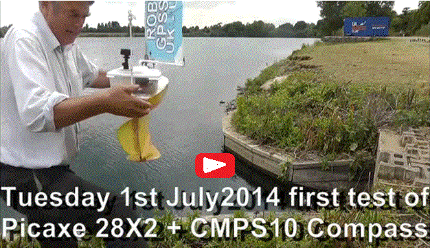 November 2017:
I liked that old Boat 6 video so much, I've added it here too. Snoopy's boats are still GPS-Only,
while we experiment with compasses. We may eventually use them :-)
Monday 28th November 2016: I've just ordered two Devantech CMPS11 Tilt-Compensated Compass at £55.12 from robot-electronics.co.uk
after seeing that the CMPS10 above was no longer available.
Usefull code from 2014 experimental work ...
readcompass: '24July14
 HIGH B.6 'switch ON the CMPS10 compass
 PAUSE FORP1SEC 'give Compass 0.1 sec to start
 SEROUT B.4, T9600_8, ( 19 ) '19 = 1x13 = get angle as two bytes 0-3590
 SERIN B.5, T9600_8, b25,b24  'get w12 0-3590 from two bytes was w6,b13,b12
 LOW B.6 'switch off compass
 w12 = w12 / 10 'degrees 0-359 was w6
 call mag2true 'convert compass to true heading in w6 now w12
 return

mag2true: 'convert magnetic compass heading in w12 (was w6) to true heading using GPS Long in b1
' values of correction from http://www.ngdc.noaa.gov/geomag-web/
'Longitude:  70W  60W  20W 1W
'50N        18.1  20.1   8.6    1.2
'40N        14.7  16.9   6.9    0.42
'20N        11.3  15.3   7.9    1.4
'Magnetic deviation if >59W then 15, else lon/4+1. 1.2 in UK, 15.3 @25N60W, 15.2@42N70W

'approximation: c = Lon / 5. True = Mag - c
 w11 = b1 'Longitude degrees. e.g. 70
 if w11 > 59 then
   w11 = 15 'correction is 15 if between 60W Microtransat Finish, and 42N70W USA.
 else
   w11 = w11 / 4
   w11 = w11 + 1 'correction is Lon/4 +1 if from UK to 60W. e.g. 1 in UK.
 endif
 'was w11 = w11 / 5 'Correction e.g. 14
 If w12>=w11 then 'e.g. 44
   w12 = w12 - w11 '45 -> 30
 else 'e.g. 4
   w12 = 360 + w12 - w11 '4 -> 350
 endif
 w2 = w12 '24July14 replace GPS heading by Compass based True heading
 return